Quantcast
Channel: Informatica Training & Tutorials
Viewing all 98 articles
Browse latest View live

Design approach to Update Huge Tables Using Oracle MERG

$
0
0
Design approach to Update Huge Tables in Informatica powercenter workflow
One of the issues we come across during the ETL design is "Update Large Tables".  This is a very common ETL scenarion especially when you treat with large volume of data like loading an SCD Type 2 Dimension.  We discussed about a design approach for this scenarion in one of our prior articles. Here in this updated article lets discuss a different approach to update Larger tables using Informatica Mapping.

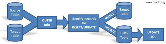
High level Design Approach.

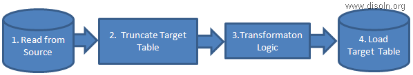
  1. Use Database JOIN to identify the records to be updated.
  2. Insert the records into TEMP table, which is identified for UPDATE.
  3. Use post session SQL to update the target table.
update-large-table-design

Design Assumption.

  1. Source and Target tables are relational table.
  2. Both source and target table is on the same database.
  3. Tables are accessible using a single database user. 

Informatica Implementation.

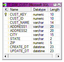
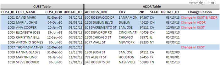
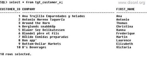
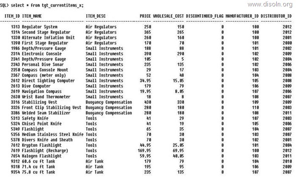
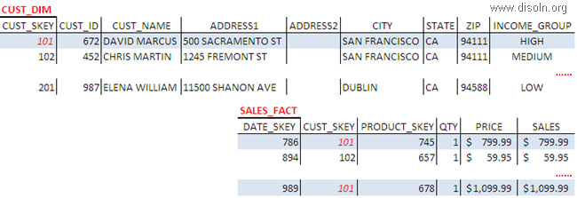
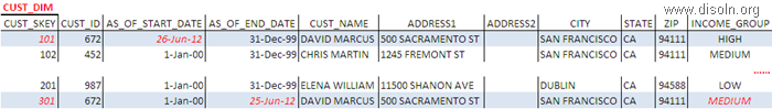
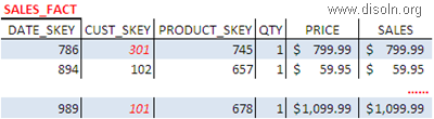
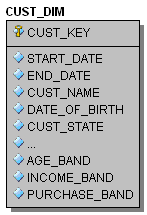
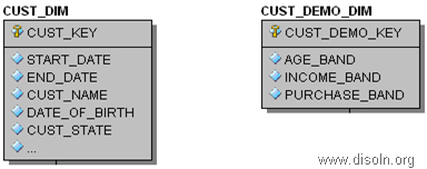
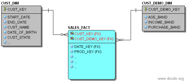
For the demonstration purpose lets consider the Customer Dimension table T_DIM_CUST, which has 100 M records. Each load we are expecting to update 100 K Records records in the Dimension table.

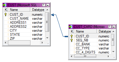
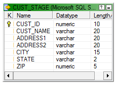
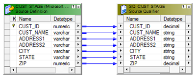
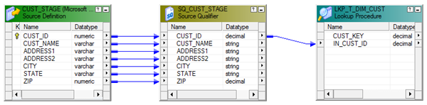
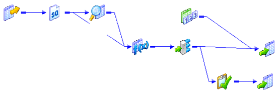
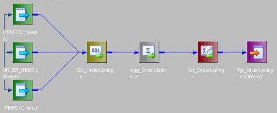
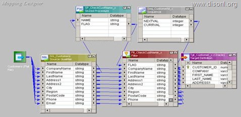
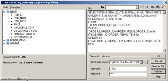
Lets start with the mapping building. As the first step, lets OUTER Join the source table CUST_STAGE and target table T_DIM_CUST. Use the SQL below as the SQL override in source qualifier. 

SELECT
--Columns From Source Tables
CUST_STAGE.CUST_ID,
CUST_STAGE.CUST_NAME,
CUST_STAGE.ADDRESS1,
CUST_STAGE.ADDRESS2,
CUST_STAGE.CITY,
CUST_STAGE.STATE,
CUST_STAGE.ZIP,
--Columns from Target Tables.
--If any column from T_DIM_CUST has NULL value, record to be set as INSERT else UPDATE
T_DIM_CUST.CUST_ID,
T_DIM_CUST.AS_OF_START_DT,
T_DIM_CUST.AS_OF_END_DT
T_DIM_CUST.CUST_NAME,
T_DIM_CUST.ADDRESS1,
T_DIM_CUST.ADDRESS2,
T_DIM_CUST.CITY,
T_DIM_CUST.STATE,
T_DIM_CUST.ZIP
FROM CUST_STAGE
--Outer Join is Used
LEFT OUTER JOIN T_DIM_CUST
ON CUST_STAGE.CUST_ID = T_DIM_CUST.CUST_ID
AND T_DIM_CUST.AS_OF_END_DT = TO_DATE('12-31-4000','MM-DD-YYYY')


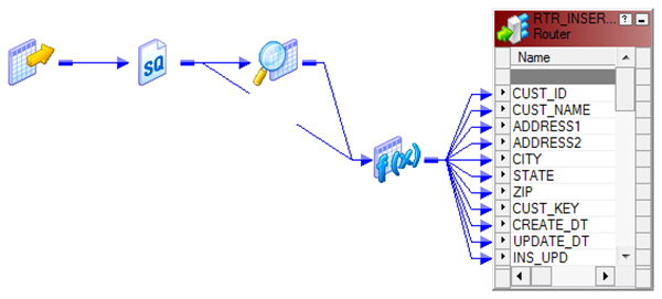
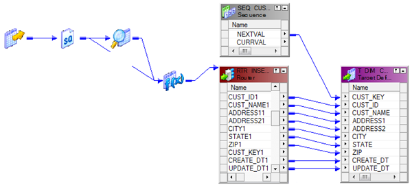
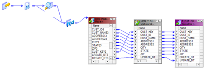
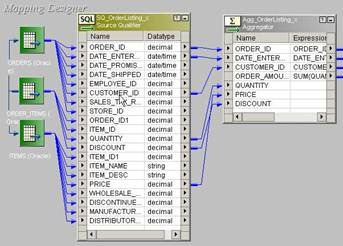
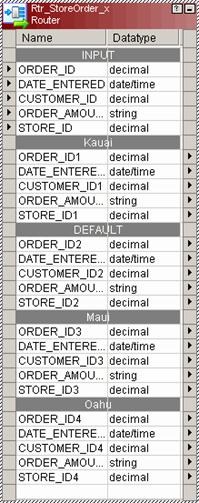
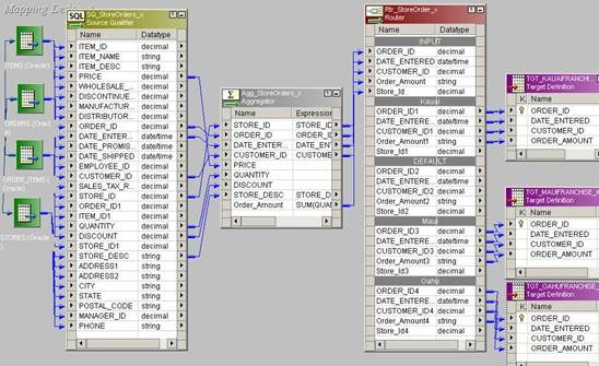
Now using a Router Transformation, route the records to INSERT/UPDATE path. Records identified as INSERT will be mapped to T_DIM_CUST and identified as UPDATE will be mapped to T_DIM_CUST_TEMP.

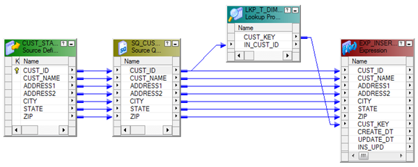
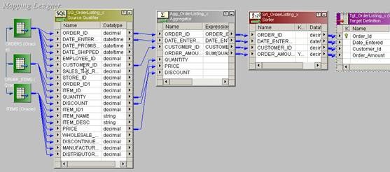
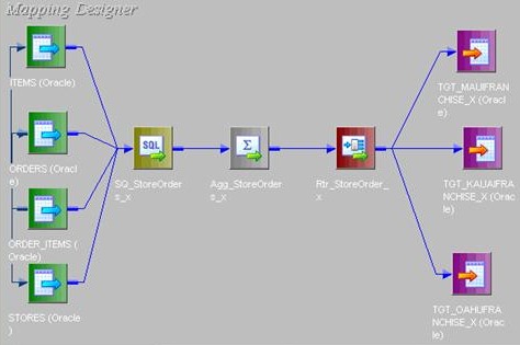
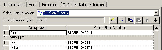
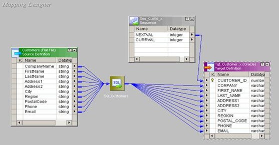
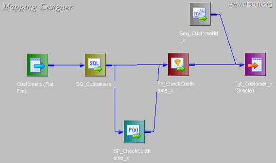
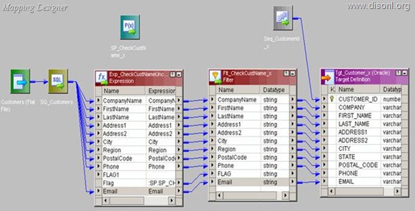
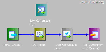
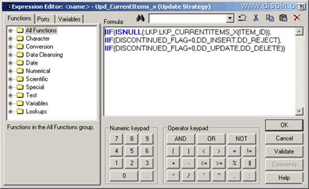
Use T_DIM_CUST_CUST_ID, which is the column from the target table to identify the records to be inserted/updated. If it is NULL, record will be set for insert else record will be set for update. Below is the Router Group Filter Condition and you can see how the mapping looks like in the below image (Below mapping image has not any transformation logic in it).
  • INSERT : IIF(ISNULL( T_DIM_CUST_CUST_ID ), TRUE, FALSE)
  • UPDATE : IIF(NOT ISNULL( T_DIM_CUST_CUST_ID ), TRUE, FALSE)

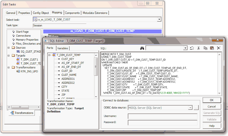
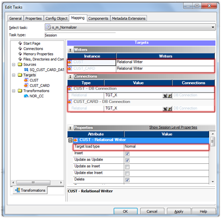
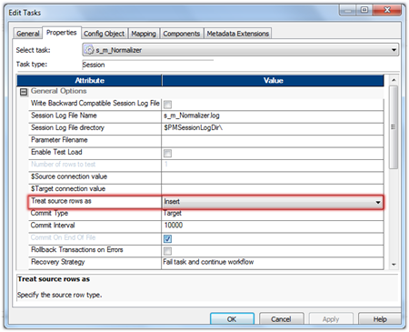
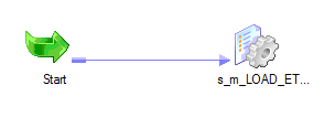
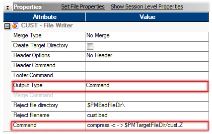
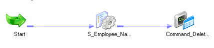
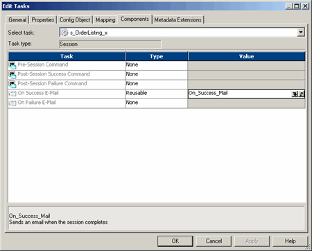
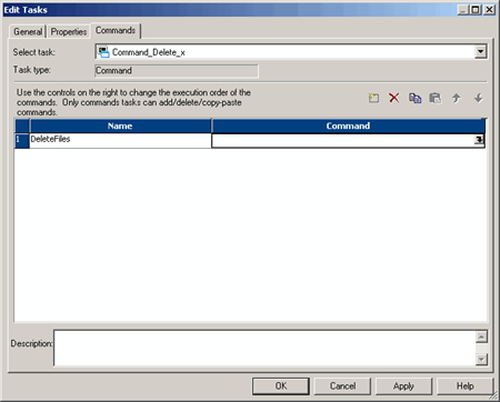
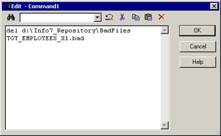
Now the mapping development is complete,  during the session configuration process, add the below SQL as part of the Post session SQL statement as shown below. This MERGE INTO SQL will update the records in T_DIM_CUST table with the values from T_DIM_CUST_TEMP.
MERGEINTO T_DIM_CUST
USING T_DIM_CUST_TEMP
ON T_DIM_CUST.CUST_ID = T_DIM_CUST_TEMP.CUST_ID
WHENMATCHEDTHEN
  UPDATE
     SET T_DIM_CUST.AS_OF_END_DT = T_DIM_CUST_TEMP.AS_OF_END_DT,
         T_DIM_CUST.UPDATE_DT    = T_DIM_CUST_TEMP.UPDATE_DT,
         T_DIM_CUST.CUST_ID      = T_DIM_CUST_TEMP.CUST_ID,
         T_DIM_CUST.CUST_NAME    = T_DIM_CUST_TEMP.CUST_NAME,
         T_DIM_CUST.ADDRESS1     = T_DIM_CUST_TEMP.ADDRESS1,
         T_DIM_CUST.ADDRESS2     = T_DIM_CUST_TEMP.ADDRESS2,
         T_DIM_CUST.CITY         = T_DIM_CUST_TEMP.CITY,
         T_DIM_CUST.STATE        = T_DIM_CUST_TEMP.STATE,
         T_DIM_CUST.ZIP          = T_DIM_CUST_TEMP.ZIP
   WHERE T_DIM_CUST.AS_OF_END_DT = TO_DATE('12-31-4000', 'MM-DD-YYYY')


That is all we need... Hope you enjoyed this design technique. Please let us know if you have any difficulties in implementing this technique.

Informatica PowerCenter Constraint Based Loading

$
0
0
Informatica PowerCenter Constraint Based Loading
Constraint based loading technique is available in Informatica PowerCenter since last couple of versions. This PowerCenter feature will let you load multiple tables in a single session, which is having database level primary key - foreign key constraint or parent - child relation. In this article let's see what is needed to set up a session for constraint based loading.

What is Constraint Based Loading

In the Workflow Manager, you can specify constraint-based loading for a session. When you select this option, the Integration Service orders the target load on a row-by-row basis. For every row, the Integration Service loads the row first to the primary key table, then to any foreign key tables.

What is Needed to Setup Constraint Based Loading

There are couple of rules for setting up Constraint-based loading in a particular session and lets see those in detail.
      1. Key Relationships.
      2. Active Source.
      3. Target Connection Groups.
      4. Treat Rows as Insert.

1. Key Relationships.

When target tables have no key relationships, the Integration Service does not perform constraint-based loading. Similarly, when target tables have circular key relationships, the Integration Service reverts to a normal load. It reverts to a normal load.

When the target definition is imported into the Target Designer, PowerCenter will detect the Key Relationship defined on the database.  You can manually create the relationship with in the Target Designer  as well.
Informatica PowerCenter Target Designer

2. Active Source.

Both the parent and child table need to be mapped from a single active source such as Source Qualifier, Aggregator, Normalizer etc. When target tables receive rows from different active sources, the Integration Service reverts to normal loading for those tables.

In the below mapping, both targets are getting rows from the active transformation Normalizer 
Informatica PowerCenter Mapping

3. Target Connection Groups.

The Integration Service enforces constraint-based loading for targets in the same target connection group. If the tables with the primary key-foreign key relationship are in different target connection groups, the Integration Service cannot enforce constraint-based loading when you run the workflow.

To verify that all targets are in the same target connection group, complete the following tasks.
  • All targets are in the same target load order group and receive data from the same active source.
  • Use the default partition properties and do not add partitions or partition points.
  • Define the same target type for all targets in the session properties.
  • Define the same database connection name for all targets in the session properties.
  • Choose normal mode for the target load type for all targets in the session properties.
    Below Image shows the target are in the same load order group.  You can verify the load order from the mapping designer.
    Target load order
    Other required properties for the Constraint Based loading is highlighted in the below image. We can set these properties in the session level from workflow manager.
    Informatica PowerCenter Session Properties

    4. Treat Rows as Insert.

    Use constraint-basedloading when the session option Treat Source Rows As is set to Insert. You might get inconsistent data if you select a different Treat Source Rows As option and you configure the session for constraint-basedloading.

    Set this property in the session level as shown in below image.
    Informatica PowerCenter session properties

    How to Setup Constraint Based Loading

    Now we now the requirements for setting up a session for constraint based target loading, Lets see how we configure the session.

    To enable constraint-basedloading, you need to set the "Constraint bases load ordering" property as shown in below image.
    Informatica PowerCenter Constraint Based Loading
    That is all we need to setup a session for constraint based target loading.

    Hope you enjoyed this article and will be helpful in your live projects. Please feel free to leave a comment or question below, we are more than happy to help.

    Informatica PowerCenter Repository Contents Upgrade

    $
    0
    0
    Informatica PowerCenter Repository Upgrade
    After an existing Informatica PowerCenter server binaries are upgraded to a higher version, we will have to upgrade the existing repository contents before we can enable the repository service and access the repository objects such as mappings, sessions, workflows etc... from the client tools. This article illustrates the step by step instructions for the upgrading the Informatica PowerCenter repository contents.

    Repository Contents Upgrade

    Step : 1
    Log on to Administrator Console using your Admin User ID and Password as shown in below image.
    Informatica PowerCenter Repository Upgrade
    Step : 2

    From the Domain Navigator Click Actions -> New -> PowerCenter Repository Service as shown below.
    Informatica PowerCenter Repository Upgrade
    Step : 3

    Provide the Repository details. 
    • Repository Name : The repository name should match with the prior version repository.
    • Description : An optional description about the repository.
    • Location : Choose the Domain you have already created. If you have only one Domain, this value will be pre populated.
    • License : Choose the license key from the drop down list.
    • Node : Choose the node name from the drop down list.
    Informatica PowerCenter Repository Upgrade
    Step : 4

    A new screen will appear, Provide the Repository database details. The repository database details should match with the prior version repository database.
    • Database Type : Choose your Repository database (Oracle/SQL Server/Sybase)
    • Username : Database user ID to connect database.
    • Password : Database user Password.
    • Connection String : Database Connection String.
    • Code Page : Database Code Page
    • Table Space : Database Table Space Name
    • Choose “Content exists under specified connection string.  Do not create new content
    Click Finish
    Informatica PowerCenter Repository Upgrade
    Step : 5

    Now you will see the added repository in the Domain Navigator.
    Choose the Repository you just added from the Domain Navigator. Click on 'Actions' at the right top, Then Actions -> Repository Contents -> Upgrade
    Informatica PowerCenter Repository Upgrade
    Step : 6

    A new window pops up. Provide the Administrator user name and password.
    Informatica PowerCenter Repository Upgrade
    Click OK to complete the upgrade. This process might take some time depending on the size of your repository.

    We are ready to enable the repository service and access the contents from the PowerCenter Client tools.

    Optimize Upgrade Performance

    before the repository contents are upgraded we need to optimize the repository contents. We can optimize the repository contents by completing the below activities.

    Purge unnecessary versions from the repository : If your repository is enabled for version control, the repository can quickly grow. If the repository is very large, purge versions that you do not need.

    Truncate the workflow and session log file : Use the Repository Manager or the pmrep TruncateLog command to truncate the workflow and session log file and delete run-time information that is not required.

    Update statistics : PowerCenter identifies and updates the statistics of all repository tables and indexes when you upgrade a repository. To increase upgrade performance, you can update the statistics before you upgrade the repository.

    SCD Type 1 Implementation using Informatica PowerCenter

    $
    0
    0
    SCD Type 1 Implementation using Informatica PowerCenter
    Unlike SCD Type 2, Slowly Changing Dimension Type 1 do not preserve any history versions of data. This methodology overwrites old data with new data, and therefore stores only the most current information. In this article lets discuss the step by step implementation of SCD Type 1 using Informatica PowerCenter.

    The number of records we store in SCD Type 1 do not increase exponentially as this methodology overwrites old data with new data  Hence we may not need the performance improvement techniques used in the SCD Type 2 Tutorial.

    Understand the Staging and Dimension Table.

    For our demonstration purpose, lets consider the CUSTOMER Dimension. Below are the detailed structure of both staging and dimension table.

    Staging Table

    In our staging table, we have all the columns required for the dimension table attributes. So no other tables other than Dimension table will be involved in the mapping. Below is the structure of our staging table.
    Informatica Source Definition

    Key Points

      1. Staging table will have only one days data. Change Data Capture is not in scope.
      2. Data is uniquely identified using CUST_ID.
      3. All attribute required by Dimension Table is available in the staging table

    Dimension Table

    Here is the structure of our Dimension table.
    SCD Type 1 Implementation using Informatica

    Key Points

      1. CUST_KEY is the surrogate key.
      2. CUST_ID is the Natural key, hence the unique record identifier.

    Mapping Building and Configuration

    Step 1
    Lets start the mapping building process. For that pull the CUST_STAGE source definition into the mapping designer.
    Slowly Changing Dymention Type 1
    Step 2
    Now using a LookUp Transformation fetch the existing Customer columns from the dimension table T_DIM_CUST. This lookup will give NULL values if the customer is not already existing in the Dimension tables.
    • LookUp Condition : IN_CUST_ID = CUST_ID
    • Return Columns : CUST_KEY
    Slowly Changing Dymention Type 1
    Step 3
    Use an Expression Transformation to identify the records for Insert and Update using below expression. 
      • INS_UPD :- IIF(ISNULL(CUST_KEY),'INS', 'UPD')    
    Additionally create two output ports.
      • CREATE_DT :- SYSDATE
      • UPDATE_DT :- SYSDATE
    See the structure of the mapping in below image.
    Slowly Changing Dymention Type 1
    Step 4
    Map the columns from the Expression Transformation to a Router Transformation and create two groups (INSERT, UPDATE) in Router Transformation using the below expression. The mapping will look like shown in the image.
      • INSERT :- IIF(INS_UPD='INS',TRUE,FALSE)
      • UPDATE :- IIF(INS_UPD='UPD',TRUE,FALSE)
    Slowly Changing Dymention Type 1

    INSERT Group

    Step 5
    Every records coming through the 'INSERT Group' will be inserted into the Dimension table T_DIM_CUST.

    Use a Sequence generator transformation to generate surrogate key CUST_KEY as shown in below image. And map the columns from the Router Transformation to the target as shown below image.
    Slowly Changing Dymention Type 1

    Note : Update Strategy is not required, if the records are set for Insert.

    UPDATE Group

    Step 6
    Records coming from the 'UPDATE Group' will update the customer Dimension with the latest customer attributes. Add an Update Strategy Transformation before the target instance and set it as DD_UPDATE. Below is the structure of the mapping.
    Slowly Changing Dymention Type 1
    We are done with the mapping building and below is the structure of the completed mapping.
    Slowly Changing Dymention Type 1

    Workflow and Session Creation

    There is not any specific properties required to be given during the session configuration.
    informatica worklet
    Below is a sample data set taken from the Dimension table T_DIM_CUST.

    Initial Inserted Value for CUSTI_ID 1003
    Slowly Changing Dymention Type 1
    Updated Value for CUSTI_ID 1003
    Slowly Changing Dymention Type 1
    Hope you guys enjoyed this. Please leave us a comment in case you have any questions of difficulties implementing this.

    Working with Aggregator and Sorter Transformation

    $
    0
    0
    Working with Aggregator and Souter Transformation
    This tutorial shows the process of creating an Informatica PowerCenter mapping and workflow which pulls data from multiple data sources and use Aggregator and Sorter Transformation. Using a sorter transformation, you can sor data either in an ascending or descending order. And aggregator can be used to summarize data. 

    For the demonstration purpose lets consider the generation of Company a report, which will show all order details in descending order of order.

    Solution

    1. Import Order, Items, Order_Items tables from the database 
    2. Calculate the total Order Amount for each Order 
    3. Create a target, which will show the total order amount in descending order 
    Below will be the structure of the completed mapping.
    Informatica Sorter transformation demo

    I. Import Source and Target Definition

    Note : Click the link to Learn more on Source Definition and Target Definition.
    1. Connect to the repository and open the project folder. 
    2. Import all the sources definitions Orders, Items, Order_Items from the database . 
    3. Create target table Tgt_OrderListing_x as shown below. 
    target definition

    II. Source Qualifier and Aggregator Transformation

    Note : Click the link to Learn more on Aggregator Transformation.
    1. Create a Source Qualifier transformation and name it SQ_OrderListing_x.
    2. Create an Aggregator transformation and group on the Order_id column
    3. Link ports ORDER_ID, DATE_ENTERED, CUSTOMER_ID, QUANTITY, PRICE, DISCOUNT into the Aggregator.
    4. Add a new output port Order_Amount.
    5. The expression for Order_Amount is SUM(PRICE * QTY – DISCOUNT)
    6. Make QUANTITY, PRICE, DISCOUNT only input ports.
    Below will the structure of the mapping at this point.
    informatica mapping

    III. Create Sorter Transformation

    1. To create the Sorter Transformation, use one of the following methods.
    • Select TRANSFORMATION | CREATE and select the Sorter transformation from the drop down. Enter the name as Srt_OrderListing_x or
    • Click on the icon Informatica Sorter transformation from the Transformations toolbar and rename the transformation to SRT_OrderListing_x.
  • Informatica Sorter transformationDrag the output ports from Aggregator transformation to Sorter
  • transformation.
  • Informatica Aggregator transformationSelect the Ports tab in the Sorter transformation as shown below. Check the Key column of the Order_Amount port and select Descending from the Direction drop down as shown below
  • Informatica Sorter transformation

    IV. Map the Target Columns

    1. Link all ports from Sorter Transformation to target table.
    2. Your mapping should look like the one as given below:
    Informatica Sorter transformation

    V. Load the Target

    1. Create a Workflow with the name wf_OrderList_x.
    2. Create a session task with the name s_OrderList_x.
    3. Run the Workflow.
    4. Monitor the Workflow.
    5. Verify the results for target table Tgt_OrderListing_x.
    Your results should look something like this.

    Hope you enjoyed this tutorial, Please let us know if you have any difficulties in trying out these exercise and subscribe to the mailing list to get the latest tutorials in your mail box.

    Working with Router Transformation and Aggregator Transformation

    $
    0
    0
    Working with Aggregator and Souter Transformation
    This tutorial shows the process of creating an Informatica PowerCenter mapping and workflow which pulls data from multiple data sources and use Aggregator and Router Transformation. Router transformation can be used to split the data into different groups. And aggregator can be used to summarize data.

    A Router transformation is similar to a Filter transformation, this transformation can be used to split the data into different groups. A Router transformation consists of input and output groups, input and output ports, group filter conditions, and properties that you configure in the Designer.

    For the demonstration purpose lets consider the generation of a report, which requires Store wise order details.

    Solution

    1. Import Items, Orders, Order-Items and Stores tables from the database. 
    2. Calculate order amount for each order for each store.
    3. Route the output based on store_id and load the data in different tables created for each store.
    4. Retrieve store wise order details.
    Below image shows the completed Mapping Layout.
    Informatica PowerCenter Router Transformation

    Create a Mapping

    I. Create Sources and Targets

    1. Import source tables from the database (Items, Orders, Order-Items and Stores).
    2. Create three target tables as shown below and name them as follows.
      • Tgt_KAUAIFRANCHISE_x
      • Tgt_MAUIFRANCHISE_x
      • Tgt_OAHUFRANCHISE_x
    3. Informatica PowerCenter Router TransformationThe ports in all three target tables are as shown below
    4. Informatica PowerCenter Router Transformation

      II. Drag Sources and Targets into the Mapping

      1. Drag all the source tables into the Mapping Designer.
      2. Create the Source Qualifier transformation and link the sources to the transformation.

      III. Create an Aggregator Transformation

      1. Drag all columns from Source qualifier into the transformation and group on Store_id and Order_id.
      2. Create an output port ORDER_AMOUNT.
      3. Create the expression: SUM(PRICE * QUANTITY - DISCOUNT)
      4. Change PRICE, QUANTITY and DISCOUNT to input ports only.

      IV. Create a Router Transformation

      1. To create a Router transformation
      • Select TRANSFORMATION | CREATE and select Router from the drop down, or
      • Click the icon from the Transformation toolbar. 
    5. Link all the output ports from Aggregator Transformation to Router Transformation
    6. Enter the name of the Router as : Rtr_StoreOrder_x.
    7. Select the Groups tab and enter the values under Group Name and Group Filter Condition as shown in the figure below.
    8. Informatica PowerCenter Router TransformationThe router transformation will generate three groups : Kauai, Maui, Oahu and a default group.
    9. Informatica PowerCenter Router TransformationLink columns from each group to the respective targets. For example, the ports under the Kauai group are linked to the Tgt_KAUAIFRANCHISE_x target. This target table contains the order details for the store where store id = 2014.
    10. The final mapping will look like one given below:
    11. Informatica PowerCenter Router Transformation

      V. Load the Target

      1. Create a Workflow with the name wf_StoresOrders_x.
      2. Create a session task with the name s_StoresOrders_x.
      3. Run the Workflow.
      4. Monitor the Workflow.
      5. Verify the results for target table Tgt_KAUAIFRANCHISE_x, Tgt_MAUIFRANCHISE_x, Tgt_OAHUFRANCHISE_x
      Hope you enjoyed this tutorial, Please let us know if you have any difficulties in trying out these exercise and subscribe to the mailing list to get the latest tutorials in your mail box.

      Source, Target Command Makes File Processing Easier than Before

      $
      0
      0
      Working with Aggregator and Souter Transformation
      Most of the time when we process flat files in Informatica PowerCenter, we do some kind of file pre or post processing, such as unzip the source file, create a custom header or footer for the target file etc. Such processing is normally done using Unix or Windows scripts, which is called using pre or post  session script. Now Informatica PowerCenter has provided Source, Target Commands to make such processing easy than before.

      File Command Property

      Using Source or Target Command property, either a Unix or a Windows command can be used to generate flat file source data input rows or file list or a session. Command writes data into stdout and PowerCenter interprets this as a file list or source data. We can use service process variables like $PMSourceFileDir in the command.

      Use Cases for File Command Property

      In this article, lets discuss couple of use cases, which can be handled easily using File Source, Target Commands. These properties can be further used as per different business needs, but lets see couple of them here.

      Use Case 1 : Read a Compressed Source File.

      Before the file is read, the file need to be unzipped.  We do not need any other pres session script to achieve this. This can be done easy with the below session setting.
      Informatica File Source Target Command Property
      This command configuration generates rows to stdout and the Flat file reader reads directly from stdout, hence removes need for staging data.

      Use Case 2 : Generating a File List.

      For reading multiple file sources with same structure, we use indirect file method. Indirect file reading is made easy using File Command Property in the session configuration as shown below.
      Informatica File Source Target Command Property
      Command writes list of file names to stdout and PowerCenter interprets this as a file list.

      Use Case 3 : Zip the Target File.

      We can zip the target file using a post session script. but this can be done with out a post session script as shown in below session configuration.
      Informatica File Source Target Command Property

      Use Case 4 : Custom Flat File Column Headings.

      You can get the column heading for a flat file using the session configuration as below. This session setting will give a file with header record 'Cust ID,Name, Street #,City,State,ZIP'
      Informatica File Source Target Command Property

      Use Case 5 : Custom Flat File Footer.

      You can get the footer for a flat file using the session configuration as given in below image. This configuration will give you a file with *****   End Of The Report   ***** as the last row of the file.
      Informatica File Source Target Command Property
      These properties can be further used as per different business needs. Hope you enjoyed this article. Please leave your comments and questions, we would like to hear from you.

      Restartability Design for Different Type ETL Loads

      $
      0
      0
      ETL Restartability design for informatica workflows
      Restartable ETL jobs are very crucial to job failure recovery, supportability and data quality of any ETL System.  So you need to build your ETL system around the ability to recover from abnormal ending of a job and restart. So a well designed ETL system should have a good restartable mechanism. In this article lets discuss  ETL restartability approaches to support different type of ETL Jobs such as Dimension loads, Fact Loads etc...

      What is ETL Restartability

      Restartability logic or recovery logic is the ability to restart ETL processing if a processing step fails to execute properly. You want the ability to restart processing at the step where it failed as well as the ability to restart the entire ETL session.

      Lets discuss  ETL restartability approaches to support commonly used ETL Jobs types.

          1. Slowly Changing Dimension
          2. Fact Table
          3. Snapshot Table
          4. Current State Table
          5. Very Large Table

      1. Slowly Changing Dimension Load

      Below diagram shows the high level steps required for SCD loading ETL Job
      Restartability Design for Different Type ETL Loads
      Lets see this in bit more detail.

      Step 1 : In this step, we will read all the data from the staging table. This will include joining data from different tables and applying any incremental data capturing logic.
      Step 2 : Data will be compared between source and target to identify if any change in any of the attributes. CHECKSUM Number can be used to make this process simple.
      Step 3 :  If the check CHECKSUM Number is different, Data is processed further, else ignored.
      Step 4 :  Do any transformation required, including the error handling.
      Step 5 :  Load the data into the Dimension Table.

      Note : Click the link to Learn more on Slowly Changing Dimension Load

      2. Fact Table Load

      High level design for the Fact Table design is given in below image.
      Restartability Design for Different Type ETL Loads
      Some more details on the high level design.

      Step 1 : In this step, we will read all the data from the source table. This will include joining data from different tables and applying any incremental data capturing logic.
      Step 2 : Perform any transformation required, including the error handling.
      Step 3 : Load the data into the TEMP Table.
      Step 4 :Load the data from the TEMP Table into the FACT table. This can be done either using Database script or using an Informatica PowerCenter session.

      Note : Data movement from the TEMP table to FACT table is assumed to be very less likely to get errors. Any error in this process will require manual intervention.

      3. Snapshot Table Load

      Many times we create snapshot tables and do build reporting on top of it. This particular restartability technique is appropriate for such scenarios. Below image shows the high level steps.
      Restartability Design for Different Type ETL Loads
      Detailed steps are as below.

      Step 1 : In this step, we will read all the data from the source table. This will include joining data from different tables and applying any incremental data capturing logic.
      Step 2 : Truncate the data from the target table.
      Step 3 : Perform any transformation required, including the error handling.
      Step 4 : Load the data into Target Table.

      4. Current State Table Load

      Just like SCD Type 1, there are scenarios, where you are interested to keep only the latest state of the data. Here we are discussing a very common and simple approach to achieve restartability for such scenarios.
      image
      More about the Steps.

      Step 1 : In this step, we will read all the data from the source table. This will include joining data from different tables and applying any incremental data capturing logic.
      Step 2 : Identify Records for INSERT/UPDATE and perform any transformations that is required, including the error handling.
      Step 3 : Insert the record which is identified for Insert.
      Step 4 : Update the record which is identified for Update.

      Note : Click the link to Learn more on Slowly Changing Dimension Load 

      5. Very Large Table Load

      The approach we are discussing here is appropriate for loading very large snapshot table , which is required to be available 24/7. You can read the complete design from this article.

      Below is the high level design.
      image
      Lets see this in bit more detail.

      Step 1 : In this step, we will read all the data from the source table. This will include joining data from different tables and applying any incremental data capturing logic.
      Step 2 : Perform any transformations that is required, including the error handling.
      Step 3 : Load the data into the TEMP Table.
      Step 4 : Rename the TEMP table to the Target table. This will move the data from the TEMP table to the actual target table. 

      Note : Click the link to Learn more on this restartability design.

      Please leave us a comment below, if you have any other thoughts or scenarios to be covered. We will be more than happy to help you.

      Sequence Generator Transformation for Unique Key Generation

      $
      0
      0
      Sequence Generator Transformation for Unique Key Generation
      The Sequence Generator transformation generates numeric values in a sequential order. Use the Sequence Generator to create unique primary key values, replace missing primary keys, or cycle through a sequential range of numbers. In this tutorial lets see a practical implementation of Sequence Generator transformation.

      For the demonstration purpose lets consider the below scenario.

      Customer source data arrives at each store in a flat file. Each file contains the customer name and other customer details. However, there is no unique id to identify each customer. The unique id for each customer will be generated through the mapping.

      Solution 

      1. Use a Sequence Generator transformation to generate a unique id for each customer.    
      2. Use this generated Customer id as the primary key in the target table.   

      Mapping Layout

      clip_image001

      I. Import Sources, Targets and create a Mapping

      Note : Click the link to Learn more on Source Definition and Target Definition.
      1. Import source definition for Customers, which is a flat file uploaded on the server.
      2. Create a target table, which is similar to the source. Add the CUSTOMER_ID port as a Primary Key. Name the target as Tgt_Customer_x.
      3. Create a mapping by the name M_Custid_x.
      4. Drag the source definition Customers and target definition for Tgt_Customer_x in the designer workspace.

      II. Drag Sources and Targets into the Mapping

      Note : Click the link to Learn more on  Mapping Designer.
      1. Drag all the source tables into the Mapping Designer.
      2. Create the Source Qualifier transformation and link the sources to the transformation.

      III. Create a Sequence Generator Transformation

      1. Create the Sequence Generator transformation.
        1. Select TRANSFORMATION | CREATE and select Sequence Generator or
        2. Click on the Informatica Powercenter Sequence Generator Transformation icon from the Transformation toolbar.
        3. Enter the name as Seq_Custid_x.
      2. Set the Start Value, End Value, Increment Value and other attributes as shown below. Check the Reset box.
      3. Informatica Powercenter Sequence Generator TransformationLink NEXTVAL column of Sequence Generator to target table.
      4. Link remaining columns from Source qualifier to target table.
      5. Your mapping should look like the one shown below.
      Informatica Powercenter Sequence Generator Transformation

      IV. Load the Target

      1. Create a Workflow with the name wf_Custid_x.
      2. Create a session task with the name s_Custid_x
      3. Run the Workflow.
      4. Monitor the Workflow.

      V. Verify the Results

      Select the data from the target table to see the results. You will see the CUSTOMER_ID starting from 1 and increasing in a sequence.
      Informatica Powercenter Sequence Generator Transformation
      Hope you enjoyed this tutorial, Please let us know if you have any difficulties in trying out these exercise and subscribe to the mailing list to get the latest tutorials in your mail box.

      Initial History Building Algorithm for Slowly Changing Dimensions

      $
      0
      0
      Initial History Building Algorithm for Slowly Changing Dimensions
      Building initial history for a Data Warehouse is a complex and time consuming task. It involve taking into account of all the date intervals from different source tables during which the source system’s representation of data in any of the tables feeding into the Dimension Tables. So we can imaging the history building complexity and the need of a reusable algorithm.

      In this article lets see a history building algorithm, which can take care of the different history building scenarios.

      History Building Date Scenarios.

      Lets see the different date scenarios. 
      1. Single Source Scenario: The Dimension Table needs only one source table to populate all its data elements. 
      2. Multiple Source Scenarios : The Dimension Table  needs multiple source tables to populate its data elements. Join conditions and ‘where’ conditions need to be applied to construct the Dimension Table row.
      3. Start & End Date Scenarios : Source table records have both start and end date to represent the active time period of any particular row.
      4. Start Date Scenarios : Source table records have only start date to represent the active time period of a particular row. This record is assumed to be active from the start date till the end of the source system existence.
      5. No Date Scenarios : Source table records have no start or end date. This record is assumed to be active for the entire life of the source system..
      The history building process involves the identification of date column interpret as system changes like create,update,delete dates. Those dates are the input, for the algorithm which we are discussing here. 

      The figure below illustrates how history dates in a potential scenario of multiple input tables and how the end result of the constructed record into Dimension Table will contain history date intervals that are more detailed than each individual source table.
      History Building Algorithm
      Note : Points on each line shows different date buckets. 

      History Building Algorithm.

      Lets understand the history building algorithm with a real time example.

      Step 1Gather all the dates from different source tables and tag as S if the date is a start date or E if the date is a end date.
      Note : Add a high date 12/31/2099 for each data source, which represents the still active record.
      History Building Algorithm
      Step 2 : Sort Dates by date and type. Date on ascending and Type on descending.
      History Building Algorithm
      Step 3 : Remove Duplicate Dates. Consider both date and type column to identify the duplicate rows.
      History Building Algorithm
      Step 4 : Set End Date to next start, Use next rows date to build the end date for the current row.
      History Building Algorithm
      Step 5 : Remove adjacent pairs. Remove start and end date pair, which is only one day apart.
      History Building Algorithm
      Step 6 : Revise Dates. If End date = Next Start date, set it to next Start Date - 1
      History Building Algorithm
      With this step we have all the time buckets created.

      We can have this algorithm build into a reusable component, which can be used across different ETL Process.

      Hope you enjoyed this tutorial, Please let us know if you have any questions and subscribe to the mailing list to get the latest tutorials in your mail box.

      Change Data Capture (CDC) Implementation for Multi Sourced ETL Processes

      $
      0
      0
      Initial History Building Algorithm for Slowly Changing Dimensions
      We have discussed couple of different options for Change Data Capture including a Change Data Capture Framework in our prior discussions. Implementing change capture for ETL process which involves multiple data source needs special care to capture changes from any of your data source. Here in this article lets see CDC implementation for ETL Process which involve multiple data sources.

      Change Scenarios

      Lets see different possible scenarios to be considered, when we implement  Change Data Capture for multi-sourced ETL.
      1. Multiple data sources : Multiple data sources may be required to generate all the data elements required for the Dimension or Target table.
      2. Change in data source : Change can be in one of the data sources or in multiple data sources. Any change needs to be captured.
      3. Parent Child Relation : Data source can have parent child relation and all parent records may not have child records.
      4. Reference & Lookup Tables : Reference and Lookup tables may be used to generate the required data elements for the Dimension or Target table.
      5. Change identification : Changed data from a data source is identified using a date column.  Any change in any of the data source will result in the change of the date column say "UPDATE_DT".
      Below chart shows the different scenarios we  mentioned above. Records to be pulled by the change data process from both CUST, ADDR tables are highlighted in blue based on the assumption that the last ETL run was 03/09/2013.
      Change Data Capture Implementation for Multi Sourced ETL Processes

      Preserving Last Run Timestamp

      We will have to store the last ETL run timestamp, so that the subsequent ETL runs can identify any changes based on the last ETL run timestamp. We have discussed couple of different options for Change Data Capture including a Change Data Capture Framework in our prior discussions. Please visit the below links for more details.
        1. Change Data Capture Made Easy Using Mapping Variables
        2. An ETL Framework for Change Data Capture
        3. Change Data Capture Implementation Using CHECKSUM Number

      Querying Changed Records

      The important part of Change Data Capture which involves multiple data source is to build an SQL query to pull all the required data. Data sources needs to be joined and queries such that any changes discussed in the above change scenarios need to be captured.

      Below SQL query is build on CUST, ADDR table, to cover all the scenarios we discusses before.

      SQL Query Option 1

                      SELECT CUST_ID,
                             CUST_NAME,
                             CUST_DOB,
                             CUST_UPDATE_DT,
                             ADDRESS_LINE,
                             CITY,
                             ZIP,
                             STATE,
                             ADDR_UPDATE_DT
                        FROM
      (SELECT C.CUST_ID AS CUST_ID,
                                     C.CUST_NAME AS CUST_NAME,
                                     C.CUST_DOB AS CUST_DOB,
                                     C.UPDATE_DT AS CUST_UPDATE_DT,
                                     A.ADDRESS_LINE AS ADDRESS_LINE,
                                     A.CITY AS CITY,
                                     A.ZIP AS ZIP,
                                     A.STATE AS STATE,
                                     A.UPDATE_DT AS ADDR_UPDATE_DT
                                FROM CUST C LEFT OUTER JOIN ADDR A ON C.CUST_ID = A.CUST_ID
      )
                       WHERE CUST_UPDATE_DT > TO_DATE ('03/09/2013', 'MM/DD/YYYY') OR
                                      ADDR_UPDATE_DT > TO_DATE ('03/09/2013', 'MM/DD/YYYY')

      How this SQL query Works

      Part 1 :  The SQL query part in RED will give all the records from both CUST and ADDR tables.
      Part 2 :  The SQL query part in BLUE will filter out records which do not have any changes.

      SQL Query Option 2

                      SELECT C.CUST_ID AS CUST_ID,
                             C.CUST_NAME AS CUST_NAME,
                             C.CUST_DOB AS CUST_DOB,
                             C.UPDATE_DT AS CUST_UPDATE_DT,
                             A.ADDRESS_LINE AS ADDRESS_LINE,
                             A.CITY AS CITY,
                             A.ZIP AS ZIP,
                             A.STATE AS STATE,
                             A.UPDATE_DT AS ADDR_UPDATE_DT
                      FROM CUST C LEFT OUTER JOIN ADDR A ON C.CUST_ID = A.CUST_ID
                      WHERE C.UPDATE_DT > TO_DATE ('03/09/2013', 'MM/DD/YYYY')

                      UNION ALL
                      SELECT C.CUST_ID AS CUST_ID,
                             C.CUST_NAME AS CUST_NAME,
                             C.CUST_DOB AS CUST_DOB,
                             C.UPDATE_DT AS CUST_UPDATE_DT,
                             A.ADDRESS_LINE AS ADDRESS_LINE,
                             A.CITY AS CITY,
                             A.ZIP AS ZIP,
                             A.STATE AS STATE,
                             A.UPDATE_DT AS ADDR_UPDATE_DT
                      FROM CUST C LEFT OUTER JOIN ADDR A ON C.CUST_ID = A.CUST_ID
                      WHERE A.UPDATE_DT > TO_DATE ('03/09/2013', 'MM/DD/YYYY')

      How this SQL query Works

      Part 1 :  The SQL query part in RED will give all the changes from CUST table and corresponding data from the ADDR table.
      Part 2 :  The SQL query part in BLUE will give all the changes from ADDR table and corresponding data from the CUST table.

      Once the data is pulled correctly from the data sources, we need to apply the ETL logic to load the Dimension or Target table.

      Hope you enjoyed this article. Please lets us know if you have any questions on this article or share us any of your experiences with change data capture.

      Stored Procedure Transformation to Leverage the Power of Database Scripts

      $
      0
      0
      Initial History Building Algorithm for Slowly Changing Dimensions
      A Stored Procedure is an important tool for populating and maintaining databases. Since stored procedures allow greater flexibility than SQL statements, database developers and programmers use stored procedures for various tasks within databases. Informatica PowerCenter provides Stored Procedure Transformation to leverage the power of Database Scripting. In this article lets see it in more in detail about how to use Stored Procedure Transformation.

      For the demonstration purpose lets consider a scenario.

      Customer source data arrives in a flat file from each store. At times, the customer names may contain some invalid data. All customer names should be validated to check for spaces, digits, special characters, etc. so that there is valid customer data in the Data Mart.

      Solution

      • Use a Stored Procedure transformation to validate the customer name.
        1. Connected Stored Procedure Transformation OR
        2. Un-Connected Stored Procedure Transformation
      • The customer name is passed as a parameter to the Stored Procedure.
      • The Stored Procedure returns a ‘V’ value for valid names and ‘I’ for invalid names.
      • Below is the layout of the completed mapping.
        Informatica PowerCenter Stored Procedure Transformation

        I. Copy the mapping

        We will be using the mapping created in the prior demo article. Copy the mapping to continue this exercise.
        1. In the Navigator Window, select the mapping M_Custid_x.
        2. Select the menu option EDIT | COPY and then select EDIT | PASTE.
        3. Rename the mapping as M_CheckCustName_x.

        II. Use a Connected Stored Procedure Transformation

        1. To create a Stored Procedure transformation
          1. Select TRANSFORMATION | CREATE and select Stored Procedure from the drop down, or
          2. Click on the Informatica PowerCenter Stored Procedure Transformation icon from the Transformation toolbar.
          3. Enter the name of the transformation as SP_CheckCustName_x.Informatica PowerCenter Stored Procedure Transformation
        2. Select the procedure name from the PROCEDURES folder.Informatica PowerCenter Stored Procedure Transformation
        3. The Stored Procedure transformation appears with two ports: Name and Flag as shown below. 
        4. Double click on the stored procedure transformation. Informatica PowerCenter Stored Procedure TransformationNote : The procedure contains two parameters, Name which is an IN parameter and FLAG, which is an OUT parameter.
        5. Delete the existing links between the Source Qualifier and Tgt_Customer_x.
        6. Link Firstname port from Source Qualifier into the Name port of the Stored Procedure transformation.
        7. Create a Filter transformation and link all ports from Source Qualifier into Filter transformation.
        8. Link the FLAG port from Stored Procedure into the Filter.
        9. Create the filter condition : FLAG = ‘V’.
        10. Link all ports except FLAG into the target.
        11. The Sequence Generator transformation will generate the Customer_id in the target. Only rows with valid customer names will pass to the target.
        12. The final mapping should look as given below:Informatica PowerCenter Stored Procedure Transformation

        III. Load the Target

        1. Create a Workflow with the name wf_CheckCustName_Connected_x.
        2. Create a session task with the name s_CheckCustName_Cconnected_x
        3. Run the Workflow.
        4. Monitor the Workflow.

        IV. Verify the Results

        Select the data from the target table. All the names are clean with no special characters or numbers.
        Informatica PowerCenter Stored Procedure Transformation

        V. Using an Unconnected Stored Procedure Transformation

        1. Using the same mapping, remove the existing Stored Procedure transformation.
        2. Create the Stored Procedure transformation again. Do not link it to any other transformation. Note : An Unconnected Stored Procedure transformation does not contain any links to other transformations.
        3. The ports in the Unconnected Stored Procedure will appear as follows :Informatica PowerCenter Stored Procedure Transformation
        4. In the same mapping, create an Expression transformation before the Filter transformation. Link relevant Ports.
        5. To call the Stored Procedure from the Expression transformation, enter the expression for the FLAG column, the newly added output port as shown below: clip_image002
        6. FirstName is passed as a parameter to the Stored Procedure and the value returned by the Stored Procedure will be available in the PROC_RESULT variable.
        7. Link all ports from Expression transformation into the filter. Complete the rest of the mapping as shown below:
        Informatica PowerCenter Stored Procedure Transformation

        IV. Load the Target

        1. Create a Workflow with the name wf_CheckCustName_Unconnected_x.
        2. Create a session task with the name s_CheckCustName_Unconnected_x
        3. Run the Workflow.
        4. Monitor the Workflow.

        Informatica PowerCenter Stored Procedure Transformation

        Hope you enjoyed this tutorial, Please let us know if you have any difficulties in trying out these exercise and subscribe to the mailing list to get the latest tutorials in your mail box.

        Data Manipulation Using Update Strategy in Informatica PowerCenter

        $
        0
        0
        Data Manipulation Using Update Strategy in Informatica PowerCenter
        It is obvious that we need data manipulation such as Insert, Update and Delete in an ETL job, Informatica PowerCenter provides Update Strategy transformation to handle any such data manipulation operations. Lets understand Update Strategy Transformation in detail.

        Lets consider a real time scenario for the demonstration.

        The operational source system that supplies data to your data mart tracks all items that your company has ever sold, even if they have since been discontinued. Your Sales Department wants to run queries against a Data Mart table that contains only currently selling items. They don’t want to use views or SQL, and they want this table updated on a regular basis.

        Solution

        1. Use the operational source table ITEMS to build a new Data Mart table, CURRENT_ITEMS, which will contain only current selling items.
        2. Create an Unconnected Lookup transformation object to match source items against current items in the Data Mart.
        3. Create an Update Strategy transformation to test the result of the lookup and determine the appropriate row action to take on the first and subsequent runs of the session.
        4. New current items will be inserted, discontinued items will be rejected, current items already in the target will be updated, and current items already in the target but discontinued since the last session run will be deleted.

        Mapping Layout

        Data Manipulation Using Update Strategy in Informatica PowerCenter

        I. Analyze the source files

        1. Use the Source Analyzer to analyze the ITEMS table from the operational source database. If the source table has already been imported and analyzed, it is not necessary to reanalyze it.

        II. Design the target schema

        1. Use the Warehouse Designer to create an automatic target definition named Tgt_CurrentItems_x using the ITEMS source definition.
        2. Create the table in the target database using your student ID and password. The table should appear as below.
        Data Manipulation Using Update Strategy in Informatica PowerCenter

        III. Create the Mapping and Transformations

        1. Use the Mapping Designer to create a mapping called M_CurrentItems_x. Drag source and target into the designer workspace.
        2. Create an Unconnected Lookup transformation to match ITEMS.ITEM_ID against Tgt_CurrentItems_x.ITEM_ID.
        3. Click on the Target button to select the Lookup table Tgt_CurrentItems_x . Click OK.
        4. Double-click on the Lookup and rename it LKP_CURRENT_ITEMS_x.
        5. Click the Ports tab.
        6. Add a new input port, ITEM_ID_IN, with the same data type as ITEM_ID.
        7. Make ITEM_ID the R port. The ports should appear as shown belowData Manipulation Using Update Strategy in Informatica PowerCenter
        8. Click the Properties tab.
        9. Verify that the database connection is set to the correct target database string. For example, $Target.
        10. Click the Condition tab.
        11. Click on the clip_image001[4] icon.
        12. Add the Lookup condition: ITEM_ID = ITEM_ID_IN.
        13. Click OK to save changes and close the Lookup transformation.

        IV. Create an Update Strategy transformation

        1. Drag all ports from Source Qualifier into Update Strategy transformation. 
        2. Test the result of the lookup and determine the appropriate row action to take on the first and subsequent runs of the session. The logic is that new current items will be inserted, discontinued items will be rejected, current items already in the target will be updated, and current items already in the target but discontinued since the last session run will be deleted.
        3. The pseudo code for the logic is as follows
          if (the record doesn’t exist in the target table) then
              if (the discontinued flag is not set) then INSERT else REJECT
                  else if (record exists) if (the discontinued flag is not set) then UPDATE
                      the record else DELETE the record

      • Create an expression for the above pseudo code and enter it in the Update Strategy expression editor. The expression will call the Unconnected Lookup transformation.
      • Data Manipulation Using Update Strategy in Informatica PowerCenter
      • Completed expression will look like in the below image.
      • Data Manipulation Using Update Strategy in Informatica PowerCenter

      • Map all the columns from the update strategy to the target table.
      • V. Load the target

        1. Use the Workflow Manager to create a Workflow wf_CurrentItems_x
        2. Session Task s_CurrentItems_x based on the M_CurrentItems_x mapping.
        3. Run and monitor the Workflow.

        VI. Verify the results

        1. Using a SQL query tool, connect to the target database and verify that the CURRENT_ITEMS table now contains data.

        2. SELECT * FROM TGT_CURRENTITEMS_X;
          The data returned from the above statement should be similar to this: Data Manipulation Using Update Strategy in Informatica PowerCenter
        3. After the session is run once the items table can be modified to simulate changes. You should run the session again to see the results of the logic code in the Update Strategy transformation.

        Video Tutorial


        Hope you enjoyed this tutorial, Please let us know if you have any difficulties in trying out these exercise.

        Re-Keying Surrogate Key For Dimension & Fact Tables. Need, Impact and Fix

        $
        0
        0
        Re-Keying Surrogate Key For Dimension & Fact Tables. Need, Impact and Fix
        A surrogate key is an artificial key that is used as a substitute for a natural key. Every surrogate key points to a dimension record, which represent the state of the dimension record at a point in time. We join between dimension tables and fact tables using surrogate keys to get the factual information at a point in time. In this article lets see the need of surrogate key re-keying, the impact of re-keying and possible fix.

        Need and Impact of Surrogate Key Re-Keying

        Typically we never re-generate or re-key surrogate key, just because of the fact that these keys links between dimension and fact records to represent the state of factual data at a point in time. At times we come across situations which can not avoid re-keying.

        Lets consider an SCD Type 1 customer dimension, which stores the basic customer information  and customer income group. And a Fact table sales fact. 
        Re-Keying Surrogate Key For Dimension and Fact Tables. The Need, Impact and Fix
        Here CUST_DIM is not keeping the historical changes of customer attributes. From this data we cannot do an analysis no how the sales per customer changed, when the income group is changed. So business users decided to keep track of the customer attributes historical changes in an SCD Type 2.

        This change in turn creates more records for each customers by adjusting the as of start and as of end date for many customer records. Here the CUST_ID 672 changed his income group from MEDIUM to HIGH, so we have two records, with surrogate key CUST_SKEY 101 and 301. One  (301) effective till 25-July-12 and the other (101) is still active.

        Changed values for both records of CUST_ID 672 is high lighted in red.
        Re-Keying Surrogate Key For Dimension and Fact Tables. The Need, Impact and Fix
        This change alone for the Dimension table will not give the capability of historical analysis. We will have to update the Fact  table to refer the correct historical Dimension record. Below shown is the correct reference from Fact table to the Dimension record.

        We can imagine how painful it will be to adjust the surrogate keys for a Fact or Dimension table having millions of records. Corrected surrogate Keys are highlighted in red in below image.
        Re-Keying Surrogate Key For Dimension and Fact Tables. The Need, Impact and Fix

        Fix for Surrogate Key Re-Keying

        By now we know the complexity involved in the re-keying of surrogate key. Lets try to find the high level steps involved in fixing the issue.

        Dimension Table

        We are not left with not much option other than recreating the Dimension table, which will involve the history building retro effectively.  To reduce the impact of Dimension rebuilding, we can build the dimension into a temporary table and finally convert the temporary table to the actual Dimension table.

        Fact Table

        Fact table can be rebuild from the source tables as long as the historical source data is available. Special care should be given to make sure that each fact record is pointing to the surrogate key, which is in effect for the time period of fact creation.

        If the historical source data is not available, we can use the existing data from Fact table to derive the new re-keyed fact table. Along with the existing Fact table join with the existing Dimension table to get the natural key and in turn join it with the new re-keyed dimension table to get the surrogate key.

        To reduce the impact of Fact rebuilding, we can build the Fact into a temporary table and finally convert the temporary table to the actual Fact table.

        Hope you enjoyed this tutorial, Please let us know if you if you have experienced re-keying crisis and how you handled the situation. We are happy to hear from you.

        Tasks and Task Developer in Informatica PowerCenter Workflow Manager

        $
        0
        0
        Re-Keying Surrogate Key For Dimension & Fact Tables. Need, Impact and Fix
        The Informatica PowerCenter Workflow Manager contains many types of tasks to help you build workflows and worklets. You can create reusable tasks in the Task Developer. Or, create and add tasks in the Workflow or Worklet Designer as you develop the workflow. In this article lets see very commonly used Tasks for Workflow or Worklet development.

        Background

        Lets Consider the scenarion.

        People, who are authorized to receive the session status, get an email, once the session has completed. The email gives details of number of rows loaded, rejected, time taken to complete, etc. The workflow should also cleanup the reject files created during a Workflow run.

        Solution

        1. Create an Email task and place it in a Workflow
        2. A Command Task can be configured to specify shell or DOS commands, to delete reject files, copy a file, or archive target files.
        3. Use the Command Task to delete reject files.

        Workflow Layout

        Below is the completed workflow layout.
        Tasks and Task Developer in  Informatica PowerCenter Workflow Manager

        I. Create an Email Task

        1. Create an Email Task in the Task Developer.
        2. Enter the name for the Email Task as On_Success_Mail.
        3. Double-click on the email task. Click on the General tab, enter the description for the task as shown below.
          Tasks and Task Developer in  Informatica PowerCenter Workflow Manager
        4. Select the Properties tab and enter the Email User Name and Email Subject details.
          Tasks and Task Developer in  Informatica PowerCenter Workflow Manager
        5. Create one more Email task, give the name as On_Failure_Mail and set its properties.

        II. Configure the Workflow

        1. Switch to the Workflow Designer and drag the wf_OrderListing_x Workflow created in Prior Article.
        2. Double-click on the Session Task s_OrderList_x.
        3. Click on the Components tab.
        4. Click On Success E-Mail option; from the drop down list select Reusable. 
          Tasks and Task Developer in  Informatica PowerCenter Workflow Manager
        5. Click on the image icon and select On_Success_Mail from the drop down list. 
          Tasks and Task Developer in  Informatica PowerCenter Workflow Manager
        6. Click on the icon image shown highlighted in the figure below.
          Tasks and Task Developer in  Informatica PowerCenter Workflow Manager
        7. Enter the email text. Here you can select any post-session built-in Email variables, useful for including important session information.
        8. The reusable Email task for On Failure E-Mail. Enter the details required.
          Tasks and Task Developer in  Informatica PowerCenter Workflow Manager
        9. Click OK.
        Note: The concerned people will receive an email regarding the status of the Workflow, subject to mail server configuration.

        III. Switch to Task Developer

        1. Create a Command task or click on the image icon on the Tasks toolbar.Tasks and Task Developer in  Informatica PowerCenter Workflow Manager
        2. Edit the Task.
        3. In the Commands tab, click on the image icon. Enter a name for the command as DeleteFiles, click on image to enter the instructions in the command.
        4. Tasks and Task Developer in  Informatica PowerCenter Workflow ManagerEnter the command as shown below.
        Tasks and Task Developer in  Informatica PowerCenter Workflow Manager

        Note: The command can be any valid UNIX command or shell script for UNIX servers, or, any valid DOS or batch file for Windows servers.

        IV. Configure the Workflow

        1. Open the Workflow wf_OrderListing_x create in Prior Article.
        2. Link the session task s_OrderList_x to Command_Delete_x.
        3. Run the Workflow.
        4. Verify the results.
        Note: The commands specified in the Command Task are executed on the Informatica Server. To verify the execution of the commands given in the Command Task you need to have privileges to login to the Informatica Server and view the BadFiles directory that has all the reject files.

        Hope you enjoyed this tutorial, Please let us know if you have any difficulties in trying out these exercise.


        SCD Type 6, a Combination of SCD Type 1, 2 and 3

        $
        0
        0
        Slowly Changing Dimension Type 6 a Combination of SCD Type 1, 2 & 3
        In couple of our previous articles, we discussed how to design and implement SCD Type1, Type 2 and Type 3. We always can not fulfill all the business requirements just by these basic SCD Types. So here lets see what is SCD Type 6 and what it offers beyond the basic SCD Types.

        Read More »

        Use Informatica Persistent Cache and Reduce Fact Table Load Time

        $
        0
        0
        Use Informatica Persistent Cache and Reduce Fact Table Load Time
        In a matured data warehouse environment, it is very common to see fact tables with dozens of dimension tables linked to it. If we are using informatica to build this ETL process, we would expect to see dozens of lookup transformations as well; unless any other design techniques are used. Since lookup is the predominant transformation, turning this will help us gain some performance. Lets see how we can use persistent lookup cache for this performance improvement.
        Read More »

        SCD Type 6 Implementation using Informatica PowerCenter

        $
        0
        0
        Slowly Changing Dimension Type 2 in Informatica powercenter workflow
        In one of our prior articles we described the SCD Type 6 dimensional modeling technique. This technique is the combination of SCD Type1, Type 2 and Type 3, which gives much more flexibility in terms of the number of queries it can answer. But off course at the cost of complexity. In this article lets discuss the step by step implementation of SCD Type 6 using Informatica PowerCenter.
        Read More »

        SCD Type 4, a Solution for Rapidly Changing Dimension

        $
        0
        0
        SCD Type 4, a Solution for Rapidly Changing Dimension
        SCD Type 2, is design to generate new records for every change of a dimension attribute, so that complete historical changes can be tracked correctly. When we have dimension attributes which changes very frequently, the dimension grow very rapidly causing considerable performance and maintenance issues. In this article lets see how we can handle this rapidly changing dimension issue using SCD Type 4.

        Lets consider a customer dimension with the following structure. Customer attributes such as Name, Date Of Birth, Customer State changes very rarely or do not even change, where as the Age Band, Income Band and Purchase Band is expected to change much frequently.

        If this Customer dimension is used by an organization with 100 million customer, can expect this dimension to grow to 200 or 300 million records assuming that there will be at least two or three changes for a customer in a year.

        SCD Type 4, a Solution for Rapidly Changing Dimension

        Add Mini Dimension

        We can split the dimension into two dimensions, one with the attributes which are less frequently changing and attributes which are frequently changing as in below. The frequently changing attributes will grouped  into the Mini Dimension. 

        SCD Type 4, a Solution for Rapidly Changing Dimension

        The Mini Dimension will contain one row for each possible combination of attributes. In our case all possible combinations of AGE_BAND, INCOME_BAND and PURCHASE_BAND will be available in CUST_DEMO_DIM with the surrogate key CUST_DEMO_KEY.

        If we have 20 different Age Bands and four different Income Bands and three Purchase Bands, we will have 20 X 4 X 3 = 2400 distinct possible combinations. These values can be populated into the Mini Dimension table once and for ever with surrogate key ranging from 1 to 2400.

        Note : Mini Dimension do not store the historical attributes, but the fact table preserved the history of dimension attribute assignment.

        Below is the model for the Customer dimension with a Mini Dimension for the Sales data mart.

        SCD Type 4, a Solution for Rapidly Changing Dimension

        Mini Dimension Challenges

        When Mini Dimension starts changing rapidly, multiple Mini Dimensions can be introduced to handle such scenarios. If no fact records are to associate main dimension and mini dimension, a fact less fact table can be used associate main dimension and mini dimension.

        Hope you guys enjoyed this. Please leave us a comment in case you have any questions of difficulties implementing this.

        Build Reusable Code in Informatica PowerCenter Using Mapplets

        $
        0
        0
        SCD Type 4, a Solution for Rapidly Changing Dimension
        Reusability is a great feature in Informatica PowerCenter which can be used by developers. Its general purpose is to reduce unnecessary coding which ultimately reduces development time and increases supportability. In this article lets see how we can build mapplet in Informatica PowerCenter to make your code reusable.

        What is Mapplet

        Mapplet is a reusable object that you create in the Mapplet Designer. It contains a set of transformations and lets you reuse the transformation logic in multiple mappings. When you use a mapplet in a mapping, you use an instance of the mapplet. Any change made to the mapplet is inherited by all instances of the mapplet.

        Solution

        Lets consider a real time scenario for the demonstration.

        The Sales Department is interested in getting both the quarterly and yearly sales. This calculation is required in multiple ETL process. So decided to create a reusable code using Mapplet.
        • Build a mapplet that uses multiple sources and aggregate functions.
        • Create a variable within the mapplet for use in the aggregate functions.

        Mapplet Layout

        Reuse Informatica PowerCenter Code Using Mapplets

        I. Set the Mapplet Designer Options

        1. Manually create a Source Qualifier to pull in data from multiple source definitions. To build a custom Source Qualifier, you must set the Mapplet Designer Options correctly.
        2. Select TOOLS | OPTIONS.
        3. Click the Format tab.
        4. In the Category section, choose Mapplet Designer from the pull-down list.
        5. In the Tables section, uncheck the Create Source Qualifiers When Opening Sources box.
        6. Click OK.

        II. Create a New Mapplet

        1. Switch to Mapplet Designer.
          1. Select TOOLS | MAPPLET DESIGNER, or
          2. Click on the clip_image001[4] button.
        2. Create a Mapplet, by selecting MAPPLETS | CREATE.
        3. Name the mapplet MPLT_QtrSales_x.

        III. Analyze the source tables.

        1. Bring the source definitions ITEMS, ORDER_ITEMS, and ORDERS into the Mapplet Designer Workspace by dragging them from the Navigator Window into the workspace.
        2. Create the Source Qualifier either from TRANSFORMATIONS | CREATE, or use the Source Qualifier icon from the transformation toolbar. Name it SQ_SalesByQtr_x.

        IV. Create an Aggregator transformation

        1. Create an Aggregator transformation and name it Agg_SalesByQtr_x
        2. Copy and link ITEM_ID and ITEM_NAME from the Source Qualifier (SQ_SalesByQtr_x) into the aggregator(Agg_SalesByQtr_x).
        3. Double-click on Agg_SalesByQtr_x to edit the Aggregator.
        4. On the Columns tab, add the following ports:
        • YEAR
        • MONTH
        • Q1SALES
        • Q2SALES
        • Q3SALES
        • Q4SALES
      • Enter the expression for YEAR as TO_CHAR(SQ_SalesByQtr_x.DATE_ENTERED,’YYYY’)
        NOTE: Notice that you now have a new input port DATE_ENTERED in your Aggregator transformation. The local input port is automatically added when the external reference made to the SQ_SalesByQtr_x is validated.
      • Build the expressions for the Variable and Output ports as follows:
      • Group records by: ITEM_ID, ITEM_NAME and YEAR.
      • Add the Aggregate functions in the expressions. Your Ports tab will look something like in below image.  
        Reuse Informatica PowerCenter Code Using Mapplets
      • Select the Properties tab.
      • Check the Sorted Input box.
      • Exit the Edit Transformation dialog box by clicking the OK button.
      • Edit the Source Qualifier.
      • You must now identify to Informatica that the data will be sorted by ITEM_ID, ITEM_NAME, and DATE_ENTERED.
        NOTE: The ports in the Source Qualifier must be in the same order as the ports in the Aggregator, in order to facilitate the correct summarization by the groupings you have specified, above.
      • Double-click the Source Qualifier transformation.
      • Select the Properties tab.
      • Open the SQL query window by clicking on the clip_image001 icon.
      • Click the Generate SQL button.
      • Append the following text to the end of the default SQL statement: ORDER BY, ITEMS.ITEM_ID, ITEMS.ITEM_NAME, ORDERS.DATE_ENTERED
        Reuse Informatica PowerCenter Code Using Mapplets
      • Enter the ODBC data source, User name, and Password given by your instructor.
      • Click the Validate button.
      • Confirm that there are no errors in the SQL.
      • Click OK to exit the SQL editor.
      • Click OK to exit the Source Qualifier Transformation.
      • V. Create a Mapplet Output Transformation

        1. Select TRANSFORMATION | CREATE or Click on the clip_image001[6] icon from the Transformations toolbar. Name it Output_SalesByQtr_x
        2. Select all of the output ports of the Aggregator and drag them into the mapplet Output transformation.
        3. Select MAPPLET | VALIDATE from the menu.
        4. Verify the results of the mapplet validation in the Output Window.
        5. Save the repository.
        We are all done and below is the completed Mapplet layout.

        Reuse Informatica PowerCenter Code Using Mapplets

        Video Tutorial


        Hope you enjoyed this tutorial, Please let us know if you have any difficulties in trying out these exercise.
        Viewing all 98 articles
        Browse latest View live