Quantcast
Channel: Informatica Training & Tutorials
Viewing all 98 articles
Browse latest View live

Understand Informatica PowerCenter Workflow Monitor

$
0
0

You can monitor workflows and tasks in the Workflow Monitor. With the Workflow Monitor, you can view details about a workflow or task in Gantt Chart view or Task view. The Workflow Monitor displays workflows that have run at least once. You can run, stop, abort, and resume workflows from the Workflow Monitor. The Workflow Monitor continuously receives information from the Integration Service and Repository Service. It also fetches information from the repository to display historic information.

Start and Monitor The Workflow

  1. If the Workflow is valid, it is ready for execution. In the Workflow Manager, use one of the following methods to start the wf_Employee_Name_x Workflow. Please use the workflow created in the exercise Understand Informatica PowerCenter Workflow Designer
    1. Select WORKFLOWS | START WORKFLOW.
    2. Right-click in the Workspace and select Start Workflow or
    3. Right-click on the wf_Employee_Name_x Workflow in the Navigator Window and select Start Workflow.
  1. To monitor a Workflow the Workflow Monitor must be opened. This is opened automatically when a workflow is executed. If this does not happen perform the following steps to start the Workflow Monitor
    1. Select Start | Programs | Informatica PowerCenter Client | Workflow Monitor.
  • To connect to Repository use one of the following methods:
  • In the Workflow Monitor Select REPOSITORY | CONNECT or
  • Click on the clip_image001 icon in the toolbar; or double-click on Repository in the Navigator Window. The Connect To Repository box appears.
    Note: Enter repository, server and login details.
  • Select the repository from the Repository pull-down list.
  • Enter the Username in the Username box.
  • Enter the Password in the Password box.
  • Enter the Hostname and Port Number details; The Host/Port Number is communication link where the Server machine is listening for client requests.

    1. Right click on the server name and select Connect.
    2. Double click on the folder to view Workflow sessions.
    3. You get two views, the Gantt Chart View and the Task View.
    Informatica PowerCenter Workflow Monitor
    1. Select the Gantt Chart tab. This view displays details about workflow runs in chronological format. It displays the following information as shown below.
    Informatica PowerCenter Workflow Monitor
    1. Select the Task View. This view displays details about workflow runs in a report format. The Status column gives the following information.
    Informatica PowerCenter Workflow Monitor
      1. A Succeeded status if the PowerCenter Server was able to successfully complete a Workflow or Task.
      2. A Failed status may occur if the PowerCenter Server failed the Workflow or Task due to fatal processing errors.
      3. A Running status if the PowerCenter Server is still processing is still processing Workflow or Task.
    1. View the Session properties by doing one of the following.
        1. Right click on the Session selected and select Properties; or
        2. Click on the Session Properties clip_image001[6] icon.
      1. The Properties tab of the S_Employee_Name_x dialog box opens. The Session should display the number of Target Success Rows as shown below.
      Informatica PowerCenter Workflow Monitor
      1. Click on the Transformation Statistics tab. More detail on the number of rows handled by the Server are shown here.
      Informatica PowerCenter Workflow Monitor
        1. Applied rows are rows the Informatica Server successfully produced and applied to the target without errors.
        2. Affected rows are generated by the Server and ‘affected to’ (or accepted by) the target.
        3. Rejected rows are either those read rows that the Server dropped during the transformation process, or, the rows that were rejected when writing to the target.
        1. View Session Log to determine what occurred during the system run. To view detailed Session information, do one of the following
          1. Right-click on the Session in the Name column and select Get Session Log.
          2. Select the Session name and click on the clip_image001[10] icon.
          Informatica PowerCenter Workflow Monitor

          Video Tutorial.

          In this demonstration video we will see how we can use Workflow Monitor.


          Hope you enjoy this tutorial, Please let us know if you have any difficulties in trying out these exercise.


          Informatica PowerCenter 9 Versioned Repository Service Configuration Guide

          $
          0
          0

          With PowerCenter Team-Based Development Option, you can create and manage multiple versions of objects, track changes, and migrate specific versions of objects from one repository to another. And this option gives you control over development environment and deployment across different environments. In this article lets see how to setup a repository service with version control enabled.

          Lets see the step by step process for configuring the Versioned Repository Service.

          If you have not already installed and configured Informatica Server and Services, Please follow this article before this Informatica PowerCenter 9 Installation and Configuration Complete Guide

          Step : 1
          Log on to Admin console using your Admin User ID and Password.

          Informatica Admin Console

          Step : 2
          Choose your Domain Name from “Domain Navigator”, Click on “Actions”, Choose “New” and “PowerCenter Repository Service”.

          Informatica Admin Console

          Step : 3 
          A new screen will appears, Provide the details as shown below.
            • Repository Name : Your Repository Name.
            • Description :  An optional description about the repository.
            • Location : Choose the Domain you have already created. If you have only one Domain, this value will be pre populated.
            • License : Choose the license key from the drop down list.
            • Node : Choose the node name from the drop down list.
          Click Next.

          Informatica Version Control Team-Based Development Option

          Step : 4
          A new screen will appear, Provide the Repository database details.
            • Database Type : Choose your Repository database (Oracle/SQL Server/Sybase)
            • Username : Database user ID to connect database.
            • Password : Database user Password.
            • Connection String : Database Connection String.
            • Code Page : Database Code Page
            • Table Space : Database Table Space Name
            • Choose “No content exists under specified connection string. Create new content”
            • Choose “Enable version control”
          Click Finish

          Informatica Version Control Team-Based Development Option

          Step : 5 
          It takes couple of minutes create Repository content. After the repository creation below screen will be seen. You can see the newly created repository in the Domain Navigator.

          Informatica Version Control Team-Based Development Option

          Step : 6 
          The repository service will be running in “Exclusive” mode as shown below. This needs to be change to “Normal” before we can connect to the repository service.

          Click “Edit” Repository Properties.

          Informatica Version Control Team-Based Development Option

          Step : 7
          A pop up window appears, Set the properties
            • Operation Mode : Normal
            • Security Audit Trail : No
          Click OK.

          Click OK for the next two pop up windows which confirms the Repository Restart to change the Repository Operating Mode.

          Informatica Version Control Team-Based Development Option

          With that we are all done with the Informatica PowerCenter versioned Repository Service configuration.  now once you create mapping, sessions, workflow or any other objects, you will have the version control options active and available under "Version" menu in each client tool.

          Hope you enjoyed this article. Please let us know your comment and feed back.

          An ETL Framework for Change Data Capture (CDC)

          $
          0
          0

          Change data capture (CDC) is the process of capturing changes made at the data source and applying them throughout the Data Warehouse. Since capturing and preserving the state of data across time is one of the core functions of a data warehouse, a change data capture framework has a very important  role in ETL design for Data Warehouses. Change Data Capture can be set up on different ways based on Timestamps on rows, Version Numbers on rows, Status indicators on rows etc. Here we will be building our framework based on "Timestamps on rows"  approach.

          In one of the our early articles, we spoke about operational meta data logging framework. Lets add on to that and build our Change Data Capture framework. We will be leveraging the capabilities provided by Informatica PowerCenter to build our framework.

          Framework Components

          Our Framework for Change Data Capture will include below components.
            1. A Relational Table :- To store the meta data.
            2. Mapping, Workflow variables : Variables to store and process latest timestamp of processed records.
            3. A Reusable Expression :- A reusable expression transformation to find latest timestamp of processed records.
            4. Pre, Post Session Command Task :- Command task to collect the meta data.
            5. Reusable Worklet :- Worklet to log the data load details into the relational table.
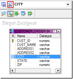
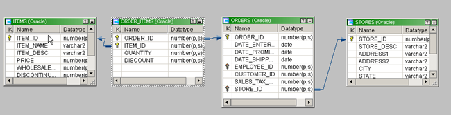
          1. Relational Table

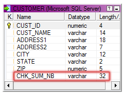
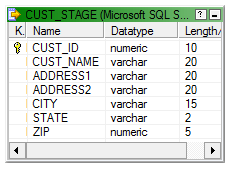
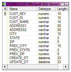
          A relation table will be used to store the operational data with the below structure. Data in this table will be retained for historical analysis.
            • ETL_JOB_NAME : ETL job name or Session name.
            • ETL_RUN_DATE : ETL job execution date.
            • DATA_START_TIME : Least timestamp of processed records
            • DATA_END_TIME : Latest timestamp of processed records
            • SRC_TABLE : Source table used in the ETL job.
            • TGT_TABLE : Target table used in the ETL job.
            • ETL_START_TIME : ETL job execution start timestamp.
            • ETL_END_TIME : ETL job execution end timestamp.
            • SRC_RECORD_COUNT : Number of records read from source.
            • INS_RECORD_COUNT : Number of records inserted into target.
            • UPD_RECORD_COUNT : Number of records updated in target.
            • ERR_RECORD_COUNT : Number of records error out in target.
            • ETL_STATUS : ETL Job status, SUCCESS or FAILURE.
            • ETL_CREATE_TIME : Record create timestamp.
            • ETL_UPDATE_TIME : Record update timestamp.

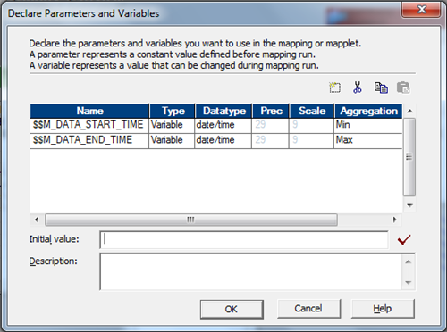
          2. Mapping and Workflow Variables

          Two mapping variables will be used to capture the least and latest timestamp of the records processed through each data load. These variables hold the time frame of the data processed.
            • $$M_DATA_START_TIME as Date/Time
            • $$M_DATA_END_TIME as Date/Time
          Additionally two workflow variables will be used to capture the least and latest timestamp of the records processed through each data load. These variables hold the time frame of the data processed.
            • $$WF_DATA_START_TIME as Date/Time
            • $$WF_DATA_END_TIME as Date/Time
          Note : Usage of these variables are described in the implementation Steps.

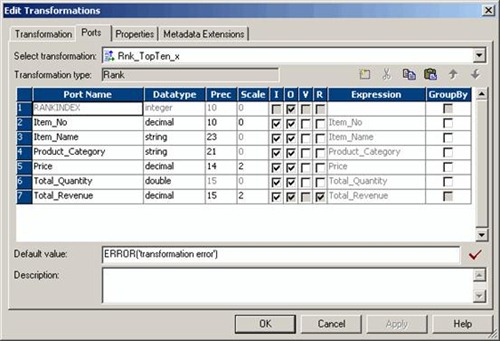
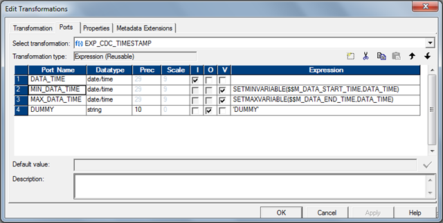
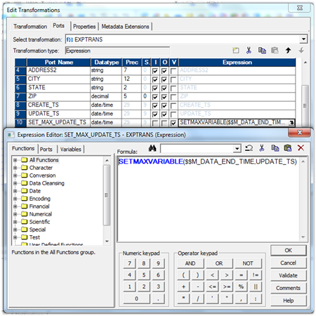
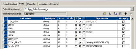
          3. Reusable Expression

          A reusable expression will be used to capture the least and latest timestamp of the records processed through each data load.

          This expression takes the timestamp column as the input based on which Change Data Capture is setup. This expression transformation will find and assign the values to the mapping variables described above.

          Below is the expression used in the transformation and the structure of the Reusable Expression Transformation.
            • SETMINVARIABLE($$M_DATA_START_TIME,DATA_TIME)
            • SETMAXVARIABLE($$M_DATA_END_TIME,DATA_TIME)
          Informatica reusable transformation

          4. Pre and Post Session Command Task

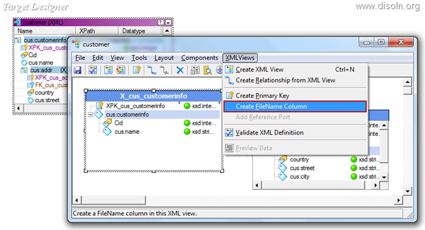
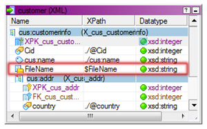
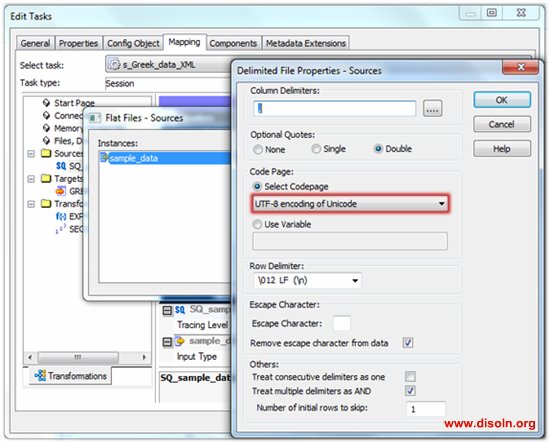
          Pre and Post session command task will be used to generate a comma delimited file with session run details. This file will be stored into $PMSourceFileDir\ directory with a name $PMWorkflowName_stat.txt

          Note :
          • $PMSourceFileDir, $PMWorkflowName are the session parameter, which gives the source file directory and name of workflow.
          • File name generated will always be <WorkflowName>_stat.txt
          The comma delimited file will have the structure as below.
            • ETL Start time
            • ETL End time
            • ETL Job name
            • Source table name
            • Target table name
            • Source record count
            • Records inserted count
            • Records updated count
            • Error record count
            • ETL Job status
          We will be using the built-in session parameters to collect session run details.
            • $PMSessionName : Name of the Informatica session.
            • $PMSourceName@TableName : Name of the source table name.
            • $PMTargetName@TableName : Name of the source table name.
            • $PMSourceQualifierName@numAffectedRows : Number of records returned from source.
            • $PMTargetName@numAffectedRows : Number of record inserted/updated into the target table.
            • $PMTargetName@numRejectedRows : Number of records error out in target.
          Note : SourceName, TargetName, SourceQualifierName will be replaced by corresponding transformation instance name used in the mapping.
          Pre Session Command Task
          Pre session command task will be used to create the file with the session start time stamp.
          echo %DATE:~10,4%-%DATE:~4,2%-%DATE:~7,2% %TIME:~0,2%:%TIME:~3,2%:%TIME:~6,2%,
          > $PMSourceFileDir\$PMWorkflowName_stat.txt
          Post Session Success Command Task
          Post session success command task will be used to append the file, which is created in the pre session command with session run details. This will capture the SUCCESS status along with other session run details.
          echo %DATE:~10,4%-%DATE:~4,2%-%DATE:~7,2% %TIME:~0,2%:%TIME:~3,2%:%TIME:~6,2%,
          $PMSessionName,
          $PMSTG_CUSTOMER_MASTER@TableName,
          $PMINS_CUSTOMER_MASTER@TableName,
          $PMSQ_STG_CUSTOMER_MASTER@numAffectedRows,
          $PMINS_CUSTOMER_MASTER@numAffectedRows,
          $PMUPD_CUSTOMER_MASTER@numAffectedRows,
          $PMINS_CUSTOMER_MASTER@numRejectedRows,
          SUCCESS,
          >> $PMSourceFileDir\$PMWorkflowName_stat.txt
          Post Session Failure Command Task
          Post session failure command task will be used to append the file, which is created in the pre session command with session run details. This will capture the FAILURE status along with other session run details.
          echo %DATE:~10,4%-%DATE:~4,2%-%DATE:~7,2% %TIME:~0,2%:%TIME:~3,2%:%TIME:~6,2%,
          $PMSessionName,
          $PMSTG_CUSTOMER_MASTER@TableName,
          $PMINS_CUSTOMER_MASTER@TableName,
          $PMSQ_STG_CUSTOMER_MASTER@numAffectedRows,
          $PMINS_CUSTOMER_MASTER@numAffectedRows,
          $PMUPD_CUSTOMER_MASTER@numAffectedRows,
          $PMINS_CUSTOMER_MASTER@numRejectedRows,
          FAILURE,
          >> $PMSourceFileDir\$PMWorkflowName_stat.txt
          Note :
          • Pre, Post session commands need to be changed based on Informatica server operating system.
          • Highlighted part of the script need to be change based on the source, target table instance name used in the mapping.

          5. Reusable Worklet

          A worklet will be created to read data from the comma delimited file generated by the pre, post session command task. In addition to the data read from the comma delimited file, the worklet takes Data Start Time and Data End Time as input parameters. Data Start Time and Data End Time is the time frame of the data processed records
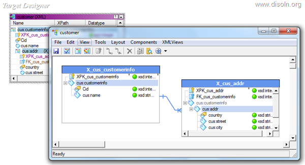
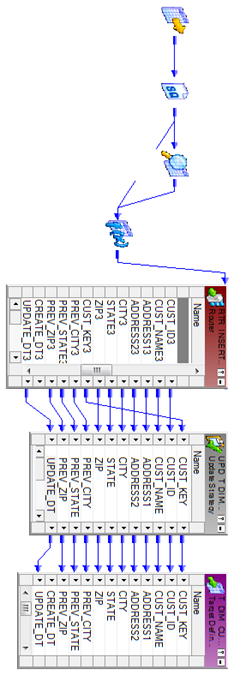
          Reusable Mapping
          A reusable mapping will be created to read data from the comma delimited file generated by the pre and post session command task.

          This mapping takes two input parameters, Create the mapping and add two mapping variables in the mapping as shown below.
            • $$M_DATA_START_TIME as Date/Time
            • $$M_DATA_END_TIME as Date/Time
          Informatica mapping variable
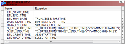
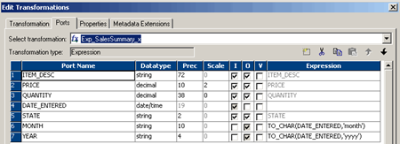
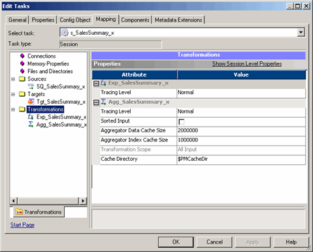
          This mapping reads data from the file generated by the Pre, Post session command task. Mapping will include an expression transformation to generate the data elements required in the target table, with below OUTPUT ports, This expression transformation takes two input ports from the source file.
            • ETL_RUN_DATE :- TRUNC(SESSSTARTTIME)
            • DATA_START_TIME :- $$M_DATA_START_TIME
            • DATA_END_TIME :- $$M_DATA_END_TIME
            • ETL_CREATE_TIME :- SESSSTARTTIME
            • ETL_UPDATE_TIME :- SESSSTARTTIME
            • O_ETL_START_TIME :- TO_DATE(LTRIM(RTRIM(ETL_START_TIME)),'YYYY-MM-DD HH24:MI:SS')
            • O_ETL_END_TIME :- TO_DATE(LTRIM(RTRIM(ETL_END_TIME)),'YYYY-MM-DD HH24:MI:SS')
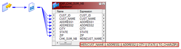
          Informatica Expression transformation
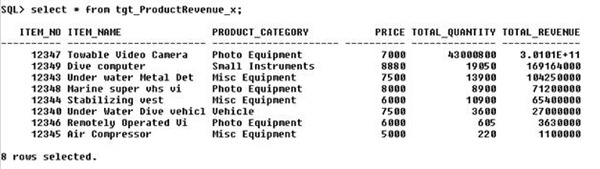
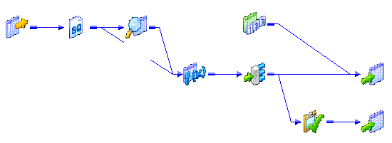
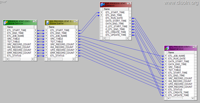
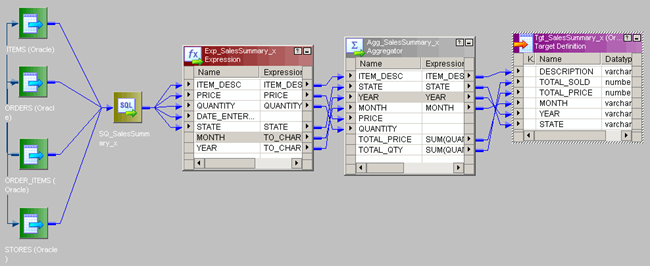
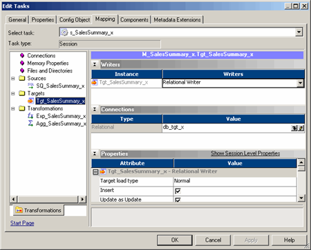
          Below is the complete mapping structure, created to populate target table 'ETL_PROCESS_STAT' 
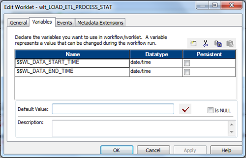
          Informatica Change Data Capture
          Reusable Worklet
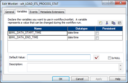
          Reusable worklet is created based on the mapping created in the last step. Create the worklet and add two worklet variables.
            • $$WL_DATA_START_TIME as Date/Time
            • $$WL_DATA_END_TIME as Date/Time
          Informatica Worklet

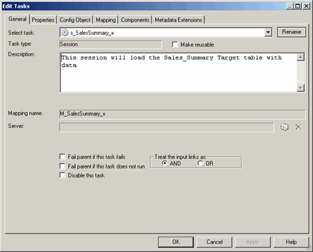
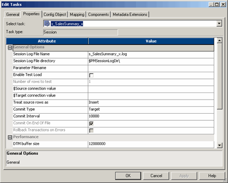
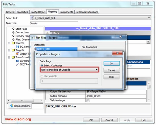
          Now create the session in the worklet, which will be configured to read data from the file created by the pre, post session command as shown below. This session is based on the reusable mapping created in the previous step.
          etl framework session

          Note : Make sure the Source File Directory and Source File name are given correctly based on the file generated by pre/post session command

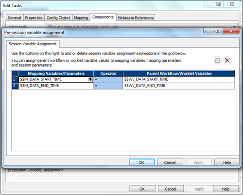
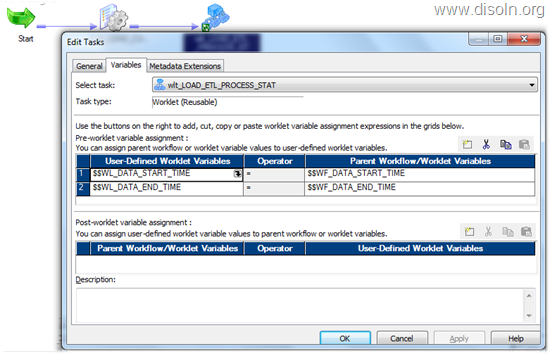
          Assign the worklet variables to the mapping variables as shown below, using the pre-session variable assignment option in the components tab.

          Informatica worklet variable assignment

          With that we are done with the configuration required for the worklet.
          informatica worklet

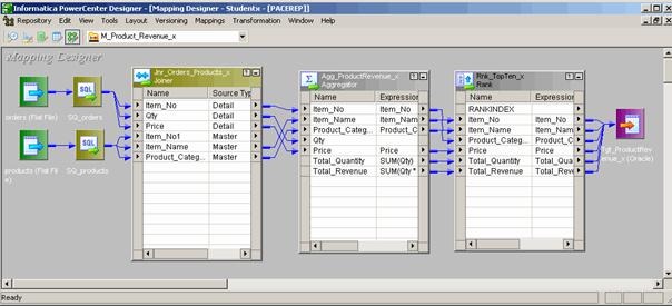
          Framework implementation in a workflow

          Now lets see how we implement the Change Data Capture Frame work in a mapping.
          Mapping
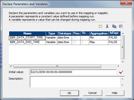
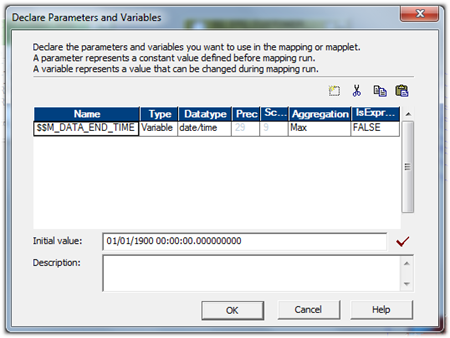
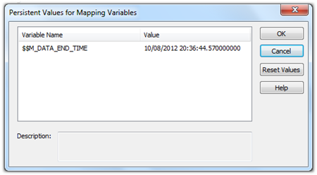
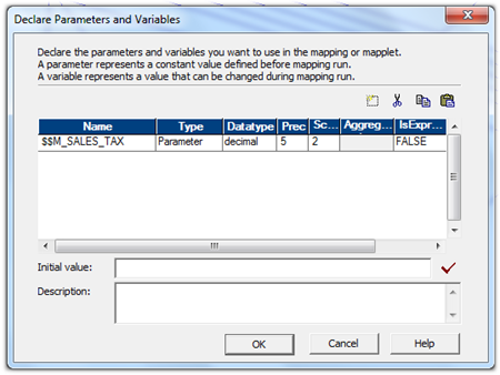
          Lets start the mapping creation and add two mapping variables as shown below.
            • $$M_DATA_START_TIME as Date/Time , Initial Value 12/31/2050 00:00:00.000000000
            • $$M_DATA_END_TIME as Date/Time , Initial Value 12/31/2050 00:00:00.000000000
          Note : Give the initial value for both the variables
          Informatica mapping variable
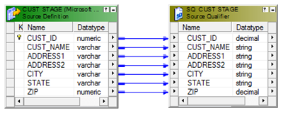
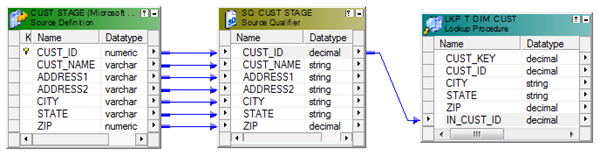
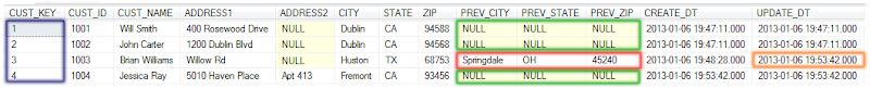
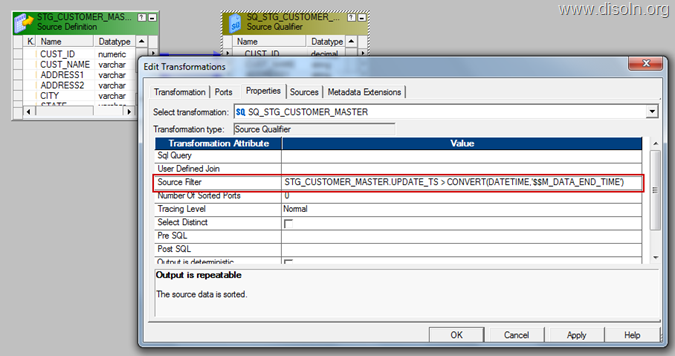
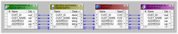
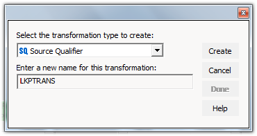
          Add source and source qualifier to the designer work space, open the source qualifier and give the filter condition to get the latest data from the source.
            • STG_CUSTOMER_MASTER.UPDATE_TS > CONVERT(DATETIME,'$$M_DATA_END_TIME')
          Hint : Use the column in the filter condition, based on which the Change Data Capture is built up on.
          Informatica Change data capture
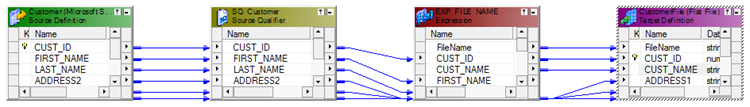
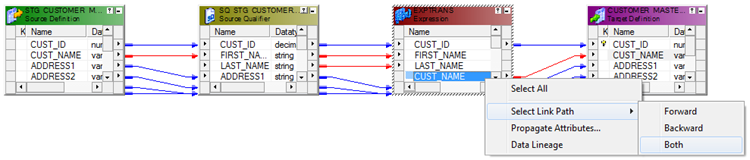
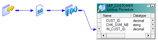
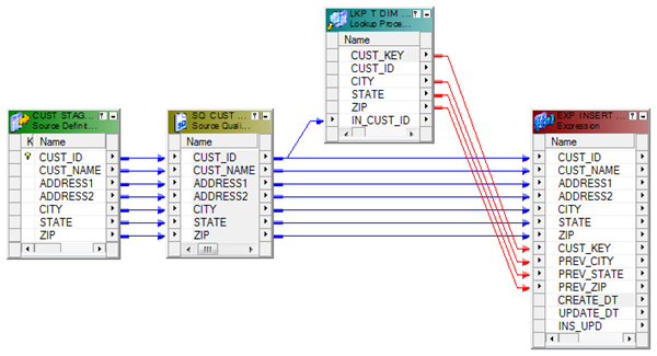
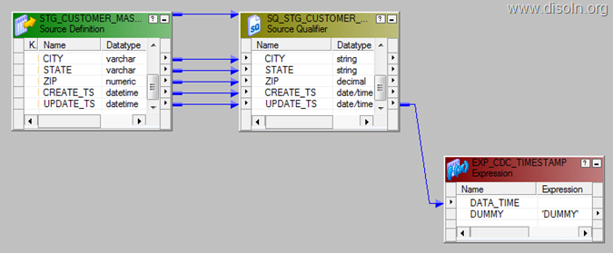
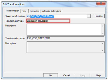
          Add the Reusable Transformation 'EXP_CDC_TIMESTAMP' to the mapping and map the column 'UPDATE_TS'  from the source qualifier to the input port of the expression.

          Hint : Use the column from the source qualifier, based on which Change Data Capture is built on. 
          Note : The reusable transformation will find the least and latest timestamp and will store in the mapping variables, which can be used in the subsequent runs.

          informatica change data capture
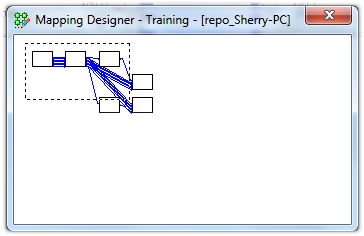
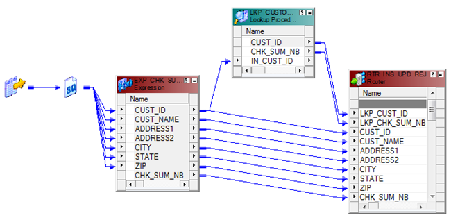
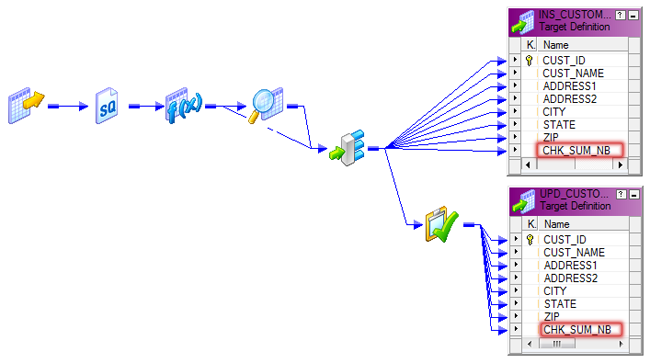
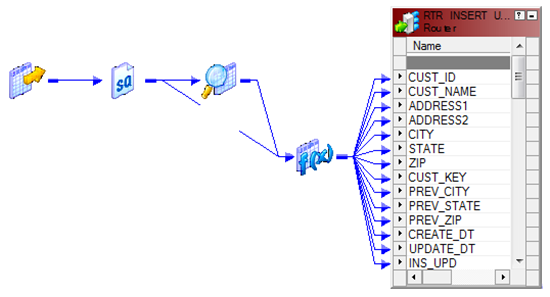
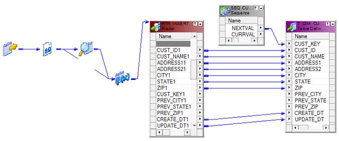
          Map the DUMMY column from 'EXP_CDC_TIMESTAMP' to the down stream transformation and complete all other transformation required in the mapping. 
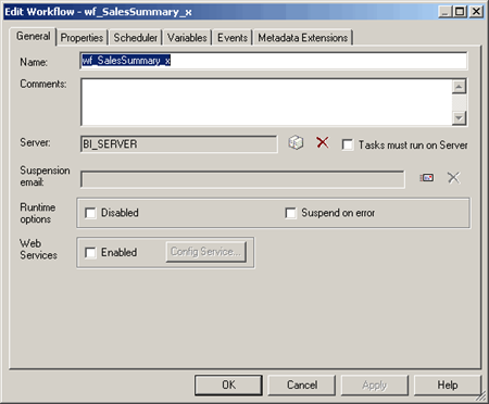
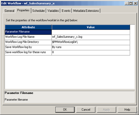
          Workflow
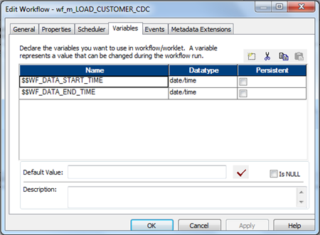
          Once the mapping is complete. lets create the workflow and add two workflow variables as shown below.
            • $$WF_DATA_START_TIME as Date/Time
            • $$WF_DATA_END_TIME as Date/Time
          informatica workflow variable
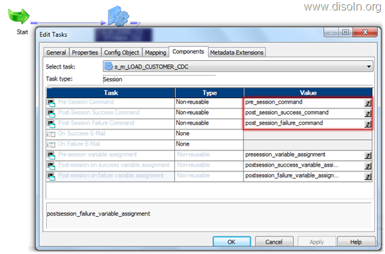
          Create the session in the workflow and add the Pre, Post session commands, which creates the flat file with the session run details.
          Informatica workflow post session command
          Now map the mapping variables to the workflow variables as below.
          Informatica workflow post session variable assignment
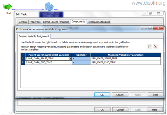
          Add the worklet to the workflow and assign the workflow variables to the worklet variable as in below image.
          Informatica worklet post session variable assignment
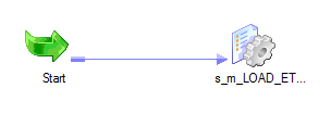
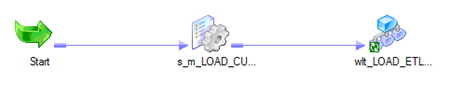
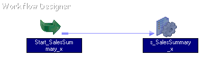
          With that we are done with the configuration. And below is the structure of the completed workflow, with Change Data Capture Framework.
          informatica workflow
          Hope you enjoyed this post.  We will be expanding this framework by adding features like notification capability, detail error capturing, change data capture etc... in the coming posts. Please leave your comments and thought about this.

          Change Data Capture (CDC) Made Easy Using Mapping Variables

          $
          0
          0

          At times we may need to implement Change Data Capture for small data integration projects which includes just couple of workflows.  Introducing a Change Data Capture framework for such project is not a recommended way to handle this, just because of the efforts required to build the framework may not be justified. Here in this article lets discuss about a simple, easy approach handle Change Data Capture.

          We will be  using Informatica Mapping Variables to building our Change Data Capture logic. Before even we talk about the implementation, lets understand the Mapping Variable

          Informatica Mapping Variable

          What is Mapping Variable
          These are variables created in PowerCenter Designer, which you can use in any expression in a mapping, and you can also use the mapping variables in a source qualifier filter, user-defined join, or extract override, and in the Expression Editor of reusable transformations.
          Mapping Variable Starting Value
          Mapping variable can take the starting value from
            1. Parameter file
            2. Pre-session variable assignment
            3. Value saved in the repository
            4. Initial value
            5. Default Value
          The Integration Service looks for the start value in the order mentioned above. Value of the mapping variable can be changed with in the session using an expression and the final value of the variable will be saved into the repository. The saved value from the repository is retrieved in the next session run and used as the session start value.
          Setting Mapping Variable Value
          You can change the mapping variable value with in the mapping or session using the Set Function. We need to use the set function based on the Aggregation Type of the variable. Aggregation Type of the variable can be set when the variable is declared in the mapping.
          • SetMaxVariable. Sets the variable to the maximum value of a group of values. To use the SetMaxVariable with a mapping variable, the aggregation type of the mapping variable must be set to Max.
          • SetMinVariable. Sets the variable to the minimum value of a group of values. use the SetMinVariable with a mapping variable, the aggregation type of the mapping variable must be set to Min.
          • SetCountVariable. Increments the variable value by one. In other words, it adds one to the variable value when a row is marked for insertion, and subtracts one when the row is marked for deletion. To use the SetCountVariable with a mapping variable, the aggregation type of the mapping variable must be set to Count.
          • SetVariable. Sets the variable to the configured value. At the end of a session, it compares the final current value of the variable to the start value of the variable. Based on the aggregate type of the variable, it saves a final value to the repository.

          Change Data Capture Implementation

          Now we understand the mapping variables, lets go ahead and start building our mapping with Change Data Capture.

          Here we are going to implement Change Data Capture for CUSTOMER data load. We need to load any new customer or changed customers data to a flat file. Since the column UPDATE_TS value changes for any new or updated customer record, we will be able to find the new or changed customer records using UPDATE_TS column.

          As the first step lets start the mapping and create a mapping variable as shown in below image.
            • $$M_DATA_END_TIME as Date/Time
          informatica mapping variable
          Now bring in the source and source qualified to the mapping designer workspace. Open the source qualifier and give the filter condition to get the latest data from the source as shown below.
            • STG_CUSTOMER_MASTER.UPDATE_TS > CONVERT(DATETIME,'$$M_DATA_END_TIME')
          [image%255B98%255D.png]

          Note : This filter condition will make sure that, latest data is pulled from the source table each and every time. Latest value for the variable $M_DATA_END_TIME is retrieved from the repository every time the session is run.

          Now map the column UPDATE_TS to an expression transformation and create a variable expression as below.
            • SETMAXVARIABLE($M_DATA_END_TIME,UPDATE_TS)
          Informatica mapping variable assignment
          Note : This expression will make sure that, latest value from the the column UPDATE_TS is stored into the repository after the successful completion of the session run.

          Now you can map all the remaining columns to the down stream transformation and complete all other transformation required in the mapping.
          Informatica Mapping
          That’s all you need to configure Change Data Capture, Now create your workflow and run the workflow. 

          Once you look into the session log file you can see the mapping variable value is retrieved from the repository and used in the source SQL, just like shown in the image below.


          You can look at the mapping variable value stored in the repository, from workflow manager. Choose the session from the workspace, right click and select 'View Persistent Value'. You get the mapping variable in a pop up window, like shown below.
          informatica mapping presistant value
          Hope you enjoyed this article. Please let us know your comment and feed back.

          User Defined Error Handling in Informatica PowerCenter

          $
          0
          0
          Informatica user defined error handling
          Error Handling is one of the must have components in any Data Warehouse or Data Integration project. When we start with any Data Warehouse or Data Integration projects, business users come up with set of exceptions to be handled in the ETL process. In this article,  lets talk about how do we easily handle these user defined error.

          Informatica Functions Used

          We are going to use two functions provided by Informatica PowerCenter to define our user defined error capture logic. Before we get into the coding lets understand the functions, which we are going to use.
              1. ERROR() 
              2. ABORT()
          ERROR() : This function Causes the PowerCenter Integration Service to skip a row and issue an error message, which you define. The error message displays in the session log or written to the error log tables based on the error logging type configuration in the session.

          ABORT() 
          : Stops the session, and issues a specified error message to the session log file or written to the error log tables based on the error logging type configuration in the session. When the PowerCenter Integration Service encounters an ABORT function, it stops transforming data at that row. It processes any rows read before the session aborts.

          Note : Use the ERROR, ABORT function for both input and output port default values. You might use these functions for input ports to keep null values from passing into a transformation and use for output ports to handle any kind of transformation error.

          Informatica Implementation

          For the demonstration lets consider a workflow which loads daily credit card transactions and below two user defined data validation checks
          1. Should not load any transaction with 0 (zero) amount, but capture such transactions into error tables
          2. Should not process any transactions with out credit card number and Stop the workflow.

          Mapping Level Changes

          To handle both the exceptions, lets create an expression transformation and add two variable ports.
          • TEST_TRANS_AMOUNT as Variable Port
          • TEST_CREDIT_CARD_NB as Variable Port
          Add below expression for both ports. First expression will take care of the user defined data validation check No 1 and second expression will take care of user defined data validation check No 2.
          • TEST_TRANS_AMOUNT :- IIF(TRANS_AMOUNT = 0,ERROR('0 (Zero) Transaction Amount'))
          • TEST_CREDIT_CARD_NB :- IIF(ISNULL(LTRIM(RTRIM(CREDIT_CARD_ND))),ABORT('Empty Credit Card Number'))
          The complete expression transformation is shown in below image.
          Informatica Error ABORT functions usage
          Now insert this transformation in the mapping where you need the data validation and complete the mapping.

          Hint :  This Expression can be converted into a Reusable transformation, So that any mapping needs this data validation can reuse this transformation.

          Session Level Changes

          Once the mapping is complete, configure the session and provide the settings for row error logging as shown in below image. Please read the article Error handling made easy using Informatica Row Error Logging for more details on row error logging.
          informatica row error logging
          With this configuration we specified, Informatica PowerCenter will create four different tables for error logging and the table details as below.
          • ETL_PMERR_DATA :- Stores data about a transformation row error and its corresponding source row.
          • ETL_PMERR_MSG :- Stores metadata about an error and the error message.
          • ETL_PMERR_SESS :- Stores metadata about the session.
          • ETL_PMERR_TRANS :- Stores metadata about the source and transformation ports, when error occurs.
          With this, we are done with the setting required to capture user defined errors.  Any data records which violates our data validation check will be captured into PMERR tables mentioned above.

          Report the Error Data.

          Now we have the error data stored in the error table, we can pull the error report using an SQL querry. Below is a basic query to get the error report. We can be more fancy with the SQL and get more information from the error tables.

          select 
                 sess.FOLDER_NAME as 'Folder Name',
                 sess.WORKFLOW_NAME as 'WorkFlow Name',
                 sess.TASK_INST_PATH as 'Session Name',
                 data.SOURCE_ROW_DATA as 'Source Data',
                 msg.ERROR_MSG as 'Error MSG'
          from 
                 ETL_PMERR_SESS sess
          left outer join ETL_PMERR_DATA data
                on data.WORKFLOW_RUN_ID = sess.WORKFLOW_RUN_ID and 
                data.SESS_INST_ID = sess.SESS_INST_ID
          left outer join ETL_PMERR_MSG msg
                on msg.WORKFLOW_RUN_ID = sess.WORKFLOW_RUN_ID and 
                msg.SESS_INST_ID = sess.SESS_INST_ID
          where 
                sess.FOLDER_NAME = <Project Folder Name> and
                sess.WORKFLOW_NAME = <Workflow Name> and
                sess.TASK_INST_PATH = <Session Name> and
                sess.SESS_START_TIME = <Session Run Time>

          Pros and Cons of this Approach.

          We should know the Pros and Cons of this approach  before applying this to your project.

          Pros.

          1. Out of the box Solution Provided by Informatica.
          2. Less Coding and Testing efforts required by the development team.

          Cons.

          1. Added overhead to the Session performance, which is expected and acceptable.

          Hope you enjoyed this article. Please leave us a comment below, if you have any difficulties implementing this error handling approach. We will be more than happy to help you.

          Update With Out Update Strategy for Better Session Performance

          $
          0
          0
          Informatica user defined error handling
          You might have come across an ETL scenario, where you need to update a huge table with few records and occasional inserts. The straight forward approach of using LookUp transformation to identify the Inserts, Update and Update Strategy to do the Insert or Update may not be right for this particular scenario, mainly because of the LookUp transformation may not perform better and start degrading as the lookup table size increases.

          In this article lets talk about a design, which can take care of the scenario we just spoke.

          The Theory

          When you configure a Informatica PowerCenter session, you have several options for handling database operations such as insert, update, delete. 

          Specifying an Operation for All Rows

          During session configuration, you can select a single database operation for all rows using the Treat Source Rows As setting from the 'Properties' tab of the session.
            1. Insert :- Treat all rows as inserts. 
            2. Delete :- Treat all rows as deletes.
            3. Update :- Treat all rows as updates. 
            4. Data Driven :- Integration Service follows instructions coded into Update Strategy flag rows for insert, delete, update, or reject. 

          Specifying Operations for Individual Target Rows

          Once you determine how to treat all rows in the session, you can also set options for individual rows, which gives additional control over how each rows behaves. Define these options in the Transformations view on Mapping tab of the session properties. 
            1. Insert :- Select this option to insert a row into a target table. 
            2. Delete :- Select this option to delete a row from a table. 
            3. Update :- You have the following options in this situation: 
          • Update as Update :- Update each row flagged for update if it exists in the target table. 
          • Update as Insert :- Insert each row flagged for update. 
          • Update else Insert :- Update the row if it exists. Otherwise, insert it. 
        1. Truncate Table :- Select this option to truncate the target table before loading data.
        2. Design and Implementation

          Now we understand the properties we need to use for our design implementation.

          We can create the mapping just like an 'INSERT' only mapping, with out LookUp, Update Strategy Transformation. During the session configuration lets set up the session properties such that the session will have the capability to both insert and update.

          First set Treat Source Rows As property as shown in below image.
          informatica session treat source as update
          Now lets set the properties for the target table as shown below.  Choose the properties Insert and Update else Insert.
          informatica session treat update else insert
          Thats all we need to set up the session for update and insert with out update strategy.

          Hope you enjoyed this article. Please leave us a comment below, if you have any difficulties implementing this. We will be more than happy to help you.

          Working With Multiple Data Sources and Aggregator Transformation

          $
          0
          0
          Informatica aggregator transformation
          This tutorial shows the process of creating an Informatica PowerCenter mapping and workflow which pulls data from multiple data sources and summarize the data using Aggregator Transformation.

          For the demonstration purpose lets consider an Inventory system maintains details of items, stock available, orders placed and customer related information. There are various requirements related to sales of an item. The company requires sales summary information.

          Lets Create an Informatica PowerCenter Workflow to get the details.
          • To get a summary of sales by item description, state and month,
          • Collect data from various relational tables sources to consolidate the information.
          • Create a relational target containing the summary wise details are created.

          I. Start the Designer

          1. Start PowerCenter Designer.
          2. Connect to a Repository and open the folder.
          3. Open the Folder where you need the mapping created.

          II. Create and verify source definitions

          1. Select SOURCES | IMPORT FROM DATABASE to import the ITEMS, ORDERS, ORDER_ITEMS and STORES tables.  Hint: Press the Ctrl key while selecting each table with a single mouse click in the Import Tables box.Informatica Source definition Import
          2. In the Source Analyzer workbook , expand the Key Types column for each source definition.
          3. Verify primary/foreign key relationships by. 
            • Verifying Key Types.
            • Observing the key relationships indicated by link lines between the tables, shown below.
          Informatica Source definition

          III. Edit source definitions

          1. In the Description window of the ORDERS source definition, enter: “This is the ORDERS source table containing all of the orders for the company” Informatica Source definition
          2. Click in the Column Name column on the ORDER_ID line and enter In the Description window : “This is the order number uniquely distinguishing one order from another.”
            Informatica Source definition
          3. Save your work.

          IV. Design a Target Schema

          Assumption: The target table does not exist in the database.
          1. Switch to Target Designer.
          2. Create a target schema from scratch and name it Tgt_SalesSummary_x. Your target should look like in the figure shown below. Informatica Source definition
          3. Create the physical table in the database so you can load data. Select the options as shown below Hint: Select TARGETS | GENERATE/EXECUTE SQL Informatica Source definition creation using SQL
          4. Click on Edit SQL file to view the script file created.
          5. Save the newly designed schema to the repository.

          V. Drag sources and create Source Qualifier Transformation

          1. Switch to Mapping Designer.
          2. In Designer’s Navigator Window, select your folder.
          3. Create a new mapping.
          4. Enter M_SalesSummary_x for the new mapping name
          5. Disable automatic creation of Source Qualifier transformation. Hint : In TOOLS | OPTIONS, click on the Format tab.Informatica designer properties 
          6. In Designer’s Navigator Window, expand the Sources section (node) in the Navigator Window, select the ITEMS, ORDER_ITEMS, ORDERS, and STORES tables and drag them to the far left side of the workspace.
          7. Create the Source Qualifier transformation .
          8. Enter the name of the transformation and click on create. Select the sources in the Select Sources for Source Qualifier Transformation. Click on OK and Done.
            Note: Blue link lines appear from the source definitions to the new Source. All columns (ports) from each of the four source definitions are linked into the new Source Qualifier.Informatica source Qualifier Transformation9. Rename the transformation to SQ_SalesSummary_x.

          VI. Drag target into the Workspace

          1. Select the Tgt_SalesSummary_x table and drag it to the far right side of the workbook.

          VII. Create the Expression transformation 

          1. Create the  expression transformation and place it to the right of the Source Qualifier transformation.
          2. Link the following ports from the SQ_SalesSummary_x to the new Expression transformation: ITEM_DESC, PRICE,  QUANTITY,  DATE_ENTERED, STATE
            Hint: Select the Link Columns icon in the toolbar .
          3. Rename the transformation to Exp_SalesSummary_x

          VIII. Use functions in the Expression transformation

          1. Click on the Ports tab.
          2. Disable the output port of DATE_ENTERED column by removing the check mark in the options box in the ‘O’ column. This will make the port an input-only port.
          3. Add a new port and name it MONTH. 
            Hint : Selecting the STATE port before clicking the icon will add the new port immediately after STATE.
          4. Disable the input port to MONTH by removing the check mark in the options box in the ‘I’ column. The Expression section of MONTH becomes eligible for editing.
          5. Add a new port Year.
          6. Let Year be an output port.
          7. On the line for MONTH, click on the downward arrow to the far right of the Expression column. This opens the Expression Editor dialog box.

          IX. Create the expression for the Month Port

          1. Enter the expression that defines MONTH in the Expression Editor.
          2. Delete the text MONTH.
          3. Select the Functions tab.
          4. Click on the ‘+’ next to Date to open the Date folder. A list of all date functions appears.
          5. Double-click the To_Char() function. The To_Char() function appears in the Formula Window.
          6. To define the port from which this function will extract the value for MONTH,select the Ports tab. All ports from all transformations in the mappings appear If you click on the ‘+’ next to each transformation
          7. Position the mouse in the parenthesis and double click the DATE_ENTERED port for the Expression transformation. DATE_ENTERED now appears within the expression you are building in the Formula: window, within the parentheses for the To_Char() function.
          8. Use the Keypad (below the Formula: window) to add a comma to the expression, after DATE_ENTERED.
          9. Then type ‘Month’. Include the single quotes.
          10. The expression is now complete. The finished expression should read: TO_CHAR(DATE_ENTERED, ‘Month’)
          11. Click Validate to parse the expression.
          12. After the expression has been parsed successfully, click OK to exit the Expression Editor.

          X. Create the expression for Year

          1. Configure the Year port in a similar fashion as the MONTH port, entering the expression : TO_CHAR(DATE_ENTERED’ ‘YYYY’)
          2. Your Ports tab will look something like the following table:Informatica source Expression Transformation
          3. Click OK to exit the Edit Transformation dialog box.

          XI. Create the Aggregator Transformation to get total price and total quantity

          1. Click on the aggregator transformation icon in the toolbar .
          2. Click the mouse to the right of Exp_SalesSummary_x. An Aggregator transformation appears.
          3. Link the following columns from Exp_SalesSummary_x to the Aggregator transformation: ITEM_DESC, PRICE, QUANTITY, STATE, MONTH, and YEAR Hint : Drag the above columns from Expression transformation into Aggregator transformation. Make sure the link columns icon is selected .
          4. Rename the transformation to Agg_SalesSummary_x
          5. Click OK.
          6. Click on the Ports tab.
          7. Disable the output ports for PRICE and QUANTITY. They will now be input-only ports.
          8. Add new ports for the TOTAL_QTY and TOTAL_PRICE. They will be output-only ports.
            Note: The values for these ports will be calculated before data leaves the Aggregator. Informatica source Aggregrator Transformation
          9. Enter expressions for these two new ports in the Expression Editor. TOTAL_QTY : SUM(QUANTITY)
            TOTAL_PRICE: SUM(QUANTITY * PRICE)
            Hint : The SUM function is found in the Aggregate folder. It is not available for use in expressions in any transformation except the Aggregator transformation.
          10. Validate the expressions.
          11. Check the GroupBy boxes on the lines for ITEM_DESC, STATE, MONTH, and YEAR These are the columns by which we want to summarize. Your Ports tab will look something like the table below:
            Note : The order of GroupBy ports should be in the sequence as shown. Select the and to move the column up and down.
          12. Click OK to exit the Edit Transformation dialog box.
          13. Link the following ports from Agg_SalesSummary_x to Tgt_SalesSummary_x
            ITEM_DESCRIPTION ->DESCRIPTION
            TOTAL_QTY –> TOTAL_QTY
            TOTAL_PRICE –> TOTAL_PRICE
            STATE –> STATE
            MONTH –> MONTH
            YEAR –> YEAR
          14. Save changes to the repository.
          15. Review the information on Designer’s Output window.
          16. As the repository is saved, the Output window will display status information relevant to the metadata you have entered into the repository.
          17. If the mapping is invalid, make changes and validate the mapping again till valid.
            Note: To save the cached output information in the Output window, select the tab so that the Output window shows messages related to the tab and select REPOSITORY | SAVE OUTPUT AS.
          18. The Final mapping will look like the one given below.
            Informatica mapping

          XII. Create a Workflow and Session Task

          1. Start the Workflow Manager, connect to the repository and open your folder.
          2. Create a Workflow. Enter the workflow name as wf_SalesSummary_x.
            Informatica workflow
          3. There are several parameters in the new workflow to be set. Under the Properties tab, note Attribute 2 displays the name of the Workflow Log File: wf_SalesSummary_x.logInformatica workflow
          4. Add a session task
            1. Create a Session task and name it s_SalesSummary_x task
            2. Select the M_SalesSummary_x mapping from the list of valid mappings and click on OK.
            3. Enter the following description and double click on the session task to edit the session properties
            4. Enter the description for the session in the General tab.Informatica session
            5. Under the Properties tab, you can enter session log file name, session log file directory, and other general session settings.Informatica session
            6. Select the Source Database Connection
            7. Select the Target Database Connection
              Informatica session
            8. Select the Mapping tab and click on the Targets folder. Under Properties, select the Target load type as Normal.
            9. Select the Transformations tab. This section lets you override individual transformation attributes. Overrides may apply to any property on any transformation used within the mapping.
              Informatica session
            10. Click OK to close the Edit Tasks dialog box.

          XIII. Link Workflow Tasks

          1. Link Start_SalesSummary_x and s_SalesSummary_x. Informatica workflow
          2. Validate the Workflow.
            1. Locate the Validate tab in the Output Window at the bottom of the Workflow Manager and view the results of the Validation checks.
            2. Repeat the validation process until the Workflow is valid.
          3. Save changes to the repository.
          4. Start the Workflow.

          XIV. Monitor a Workflow

          1. Open Workflow Monitor.
          2. Select the Gantt Chart tab
          3. Double-click on the folder to view the previously processed workflows Drill down by double clicking on each object all the way until the session task s_SalesSummary_x, appears. Informatica workflow monitor
          4. Note the status of the s_SalesSummary_x session task.
          5. View the Session properties and check if it displays the number of Target Success Rows as shown below: Informatica workflow monitor
          6. Click on the Transformation Statistics tab. More detail on the number of rows handled by the Server are shown here: Informatica workflow monitor
          7. View Session Log and read the messages.

          Video Tutorial


          Hope you enjoy this tutorial, Please let us know if you have any difficulties in trying out these exercise.

          11 Ways to Make Informatica PowerCenter Code Reusable

          $
          0
          0
          Informatica reusable objects
          Reusability is a great feature in Informatica PowerCenter which can be used by developers. Its general purpose is to reduce unnecessary coding which ultimately reduces development time and increases supportability. In this article lets see different options available in Informatica PowerCenter to make your code reusable.
                1. Mapplet
                2. Reusable Transformation
                3. Shared Folder
                4. Global Repository
                5. Worklet
                6. Reusable Session
                7. Reusable Tasks
                8. Mapping Parameter
                9. Mapping Variable
                10. WorkFlow Variable
                11. Worklet Variable

          1. Mapplet

          Mapplet is a reusable object that you create in the Mapplet Designer. It contains a set of transformations and lets you reuse the transformation logic in multiple mappings. When you use a mapplet in a mapping, you use an instance of the mapplet. Any change made to the mapplet is inherited by all instances of the mapplet.

          If you have several fact tables that require a series of dimension keys, you can create a mapplet containing a series of Lookup transformations to find each dimension key. You can then use the mapplet in each fact table mapping.
          Informatica Mapplet

          2. Reusable Transformation

          Reusable Transformations can be created in Transformation Developer and can be reused in multiple mappings. When you use a reusable transformation in a mapping, you use an instance of the transformation. Any change made to the transformation is inherited by all its instances.

          If you have a business rule to trim spaces from customer name and customer address columns, then you can create a reusable expression transformation to trim spaces from the column, which can be reused in multiple mappings.
          Informatica Reusable Transformation

          3. Shared Folder

          A Shared folder can be created in a Repository from the repository manager. The objects from the shared folder can be accessed using shortcuts from different folders in the same Repository.

          You can create all the reusable framework objects (CDC Framework, Error Handling Framework etc...) in the Shared Folder  and can be accessed using shortcuts from different folders in the same  repository.
          Informatica PowerCenter Shared Folder

          4. Global Repository

          A Global Repository can be created in a Repository Domain which is linked to multiple Local Repositories. An object created in the Global Repository is accessible from the Local Repositories using the shortcuts created to the global objects. Any change in the Global Repository Object will be inherited to all the shortcut objects.

          You can create all the reusable framework objects (CDC Framework, Error Handling Framework etc...) in the Global Repository and can be accessed using shortcuts from different local repositories.
          Informatica PowerCenter Object Shortcut

          5. Worklet

          A worklet is an object created by combining set of tasks to build a workflow logic. Worklet can be reused in multiple  workflows, which can be configured to run concurrently. You can create a worklet in the Worklet Designer.

          Reusable worklet implemented in the Change Data Capture Framework, which is discussed in one of our prior article is a practical  application of worklet.
          Informatica PowerCenter Worklet Designer

          6. Reusable Session

          A session is a set of instructions that tells the Integration Service how and when to move data from sources to  targets. You can create a reusable Session task in the Task Developer. A reusable session can be used multiple workflows and even in a worklet.

          Reusable session used in the Operational Metadata Logging Framework, which is discussed in one of our prior article is a practical  implementation of reusable session.
          Informatica PowerCenter Reusable Session

          7. Reusable Tasks

          Apart from the reusable session task, we can create reusable email task and reusable command task in the Task  Developer. We can reuse these reusable tasks in multiple workflows and worklets.

          A reusable email task can be used to create a standard session failure email notification, which can be reused in different session tasks.
          Informatica PowerCenter Task Developer

          8. Mapping Parameter

          Define values that remain constant throughout a session, such as state sales tax rates. When declared in a mapping or mapplet, $$ParameterName is a user-defined mapping parameter.
          Informatica Mapping Parameter

          9. Mapping Variable

          Define values that can change during a session. The Integration Service saves the value of a mapping variable to the repository at the end of each successful session run and uses that value the next time you run the session. When declared in a mapping or mapplet, $$VariableName is a mapping variable.
          Informatica Mapping variables

          10. WorkFlow Variable

          You can create user defined workflow variables to pass variable values between mapping, sessions within a workflow. Even if the workflow variables alone do not give code reusability, it works with other components to provide reusability.
          Informatica Workflow Variables

          11. Worklet Variable

          User defined worklet variables can be create in worklets to pass values between mapping, sessions, worklets within a workflow. Worklet variables by itself do not give code reusability, but it works with other components to facilitate code reusability. Informatica Worklet Variables
          In addition to the parameters and variables mentioned above, Informatica PowerCenter provides much more type of Variables and Parameters, which provide more flexibility to build reusable code, such as
            • Service variables.
            • Service process variables.
            • Session parameters.
            • $Source. $Target connection variables.
            • Email variables.
            • Local variables.
            • Built-in variables.
          Hope you enjoyed this post. Please leave your comments and share how you use these features in your projects.

          Working with Flat File Source, LookUp & Filter Transformation

          $
          0
          0
          Informatica LookUp Transformation
          This tutorial shows the process of creating an Informatica PowerCenter mapping and workflow which pulls data from Flat File  data sources and use LookUp and Filter Transformation.


          For the demonstration purpose lets consider a flat file with the list of existing and potential customers. We need to create a mapping which loads only the potential customers but not the existing customers to a relational target table.

          While creating the mapping we will cover the following.
          • Create a mapping which reads from a flat file and creates a relational table consisting of new customers
          • Analyze a fixed width flat file
          • Configure a Connected Lookup transformation
          • Use a Filter transformation to exclude records from the pipeline.

          I. Connect to the Repository

          1. Connect to the repository.
          2. Open the folder where you need the mapping built.

          II. Analyze the source files

          1. Import the flat file definition (say Nielsen.dat) into the repository.
          2. Select SOURCES | IMPORT FROM FILE from the menu.
          3. Select Nielsen.dat from the source file directory path. Hint : Be sure to set the Files of type: to All files (*.*) from the pull-down list, before clicking on OK.
            1. Set the following options in the Flat File Wizard:
            2. Select Fixed Width and check the Import field names from first line box. This option will extract the field names from the first record in the file. Informatica PowerCenter flat file Configuration
            3. Create a break line or separator between the fields.
            4. Click on NEXT to continue. Informatica PowerCenter flat file Configuration
            5. Refer Appendix A to see the structure of NIELSEN.DAT flat file. Informatica PowerCenter flat file Configuration
          4. Change field name St to State and Code to Postal_Code. Note : The physical data file will be present on the Server. At runtime, when the Server is ready to process the data (which is now defined by this new source definition called Nielsen.dat) it will look for the flat file that contains the data in Nielsen.dat.
          5. Click Finish.
          6. Name the new source definition NIELSEN. This is the name that will appear as metadata in the repository, for the source definition.

          III. Design the Target Schema

          Assumption: The target table does not exist in the database
          1. Switch to Target Designer.
          2. Select EDIT | CLEAR if necessary to clear the workspace. Any objects you clear from the workspace will still be available for use in Designer’s Navigator Window, in the Targets node.
          3. Drag the NIELSEN source definition from the Navigator Window into the workspace to automatically create a target table definition. You have just created a target definition based on the structure of the source file definition. You now need to edit the target table definition.
          4. Rename the table as Tgt_New_Cust_x.
          5. Informatica PowerCenter target Configuration
          6. Enter the field names as mentioned in the Figure below .Change the Key Type for Customer_ID to Primary Key. The Not Null option will automatically be checked. Save the repository.
          7. The target table definition should look like this Informatica PowerCenter target Configuration
          8. Create the physical table in the Oracle Database so that you can load data. Hint : From the Edit table properties in Target designer, change the database type to Oracle. Informatica PowerCenter target Configuration

          IV. Create the mapping and drag the Source and Target

          1. Create a new mapping with the name M_New_Customer_x
          2. Drag the source into the Mapping Designer workspace. The SourceQualifier should be automatically created.
          3. Rename the Source Qualifier as SQ_NIELSEN_x
          4. Drag the target (Tgt_New_Cust_x) into the Mapping Designer workspace

          V. Create a Lookup Transformation

          1. Select TRANSFORMATION | CREATE.
          2. Select Lookup from the pull-down list.
          3. Name the new Lookup transformation Lkp_New_Customer_x. Informatica PowerCenter lookup Configuration
          4. You need to identify the Lookup table in the Lookup transformation. Use the CUSTOMERS table from the source database to serve as the Lookup table and import it from the database.
          5. Select Import to import the Lookup table. Informatica PowerCenter lookup Configuration
          6. Enter the ODBC Data Source, Username, Owner name, and Password for the Source Database and Connect.
          7. In the Select Tables box, expand the owner name until you see a TABLES listing.
          8. Select the CUSTOMERS table.
          9. Click OK.
          10. Click Done to close the Create Transformation dialog box. Informatica PowerCenter lookup ConfigurationNote : All the columns from the CUSTOMERS table are seen in the transformation.
          11. Create an input-only port in Lkp_New_Customer_x to hold the Customer_Id value, coming from SQ_NIELSEN_x .
            1. Highlight the Cust_Id column from the SQ_NIELSEN_x
            2. Drag/drop it to Lkp_New_Customer_x.
            3. Double-click on Lkp_New_Customer_x to edit the Lookup transformation.
            4. Click the Ports tab, make Cust_Id an input-only port.
            5. Make CUSTOMER_Id a lookup and output port. Informatica PowerCenter lookup Configuration
          12. Create the condition for lookup.
            1. Click the Condition Tab.
            2. Click on the    icon.
            3. Add the lookup condition: CUSTOMER_ID = Cust_Id.
              Note : Informatica takes its ‘best guess’ at the lookup condition you intend, based on data type and precision of the ports now in the Lookup transformation. Informatica PowerCenter lookup Configuration
          13. Click the Properties tab.
          14. At line 6 as shown in the figure below, note the Connection Information.
            Informatica PowerCenter lookup Configuration

          VI. Create a Filter Transformation

          1. Create a Filter transformation that will filter through those records that do not match the lookup condition and name it Fil_New_Cust_x.
          2. Drag all the ports from Source Qualifier to the new Filter. The next step is to create an input-only port to hold the result of the lookup.
          3. Highlight the CUSTOMER_ID port from Lkp_New_Customer_x .
          4. Drag it to an empty port in Fil_New_Cust_x .
          5. Double-click Fil_New_Cust_x to edit the filter.
          6. Click the Properties tab.
          7. Enter the filter condition: ISNULL(CUSTOMER_ID). This condition will allow only those records whose value for CUSTOMER_ID is = null, to pass through the filter.
          8. Click OK twice to exit the transformation.
          9. Link all ports except CUSTOMER_ID from the Filter to the Target table.
            Hint : Select the LAYOUT | AUTOLINK menu options, or right-click in the workspace background, and choose Auto link. In the Auto link box, select the Name radio button. This will link the corresponding columns based on their names.
            Informatica PowerCenter mapping Configuration
          10. Click OK.
          11. Save the repository.
          12. Check the Output window to verify that the mapping is valid.
          13. Given below is the final mapping.
          Informatica PowerCenter mappingConfiguration

          VII.    Create the Workflow and Set Session Tasks Properties

          1. Launch the Workflow Manager and connect to the repository.
          2. Select your folder.
          3. Select WORKFLOWS | CREATE to create a Workflow as wf_New_Customer_x.
          4. Select TASKS | CREATE to d create a Session Task as s_New_Customer_x.
          5. Select the M_New_Customer_x mapping.
          6. Set the following options in the Session Edit Task:
            1. Select the Properties tab. Leave all defaults.
          7. Select the Mapping tab.
            1. Select the Source folder. On the right hand side, under Properties, verify the attribute settings are set to the following:
              1. Source Directory path = $PMSourceFileDir\
              2. File Name = Nielsen.dat (Use the same case as that present on the server)
              3. Source Type: Direct
                Note : For the session you are creating, the Server needs the exact path, file name and extension for the file as it resides on the Server, to use at run time
            2. Click on the Set File Properties button. Informatica PowerCenter Session Configuration
            3. Click on Advanced. 
              Informatica PowerCenter Session file Configuration
            4. Check the Line sequential file format check box.
              Informatica PowerCenter Session file Configuration
            5. Select the Targets folder. 
              1. Under Connections on the right hand side, Select the value of
                Target Relational Database Connection.
            6. In the Transformations Folder, Select the Lkp_New_Customer transformation.
              1. On the right hand side, in Connections, Select the Relational Database Connection for the Lookup Table. Figure
                Informatica PowerCenter Session Configuration
          8. Run the Workflow.
          9. Monitor the Workflow.
          10. View the Session Details and Session Log.
          11. Verify the Results from the target table by running the query SELECT * FROM Tgt_New_Cust_x;

          Video Tutorial


          Hope you enjoy this tutorial, Please let us know if you have any difficulties in trying out these exercise.

          Unlock the JOINER Transformation Limitations Using ACTIVE LookUp

          $
          0
          0
          Informatica user defined error handling
          Joiner Transformation can be used to achieve the functionality of SQL join Operation including  full outer join. Additionally we can use Joiner to join data from heterogeneous data sources. But it is limited with the operators, which can be used in the join condition, it can use only equal (=) condition in the join. In this article lets see how we can unlock this limitation using Informatica PowerCenter Active LookUp transformation.

          To overcome this disability we will be using Active LookUp Transformation, which is available from Informatica PowerCenter Version 9x.

          What is Active LookUp

          From Informatica PowerCenter Version 9x onwards we can configure the lookup transformation to return all the rows from the lookup table matching the lookup condition. This Lookup transformation becomes an active transformation. For the Active LookUp 'Lookup Policy on Multiple Match' property will be 'Use All Values'. This property becomes read-only and cannot be changed after the transformation is created.

          How to Configure Active LookUp

          Just like any other transformation start creating the transformation.
          Informatica powerCenter Active Lookup
          Choose the LookUp Table from the popup window and select 'Return All Values on Multiple Match'. This property will set the lookup as active lookup transformation.
          Informatica powerCenter Active Lookup
          From the properties tab you can see the 'Lookup Policy on Multiple Match' property is set as 'Use All Values' and it is a read only property and cannot be changed after the transformation is created.
          Informatica powerCenter Active Lookup

          Unlock the JOINER Transformation Limitations

          Lets consider a simple scenario where you are given with flat file with a list of customers and you need to pull all the orders from the relational table by a customer from a give date.

          We can not use JOINER transformation to combine these two data sources and get all the orders form a customer just because of the fact that, we need to use greater than (>) operator to get all the records and only equal (=) operator is supported in JOINER.

          So we can create the mapping with the Active LookUp Transformation to over come the limitation.

          After the source definition is pulled into the designer, create the lookup transformation as shown below. Select 'Return All Values on Multiple Match'. to set the Active LookUp. 

          Informatica powerCenter Active Lookup
          From the properties tab you can see the 'Lookup Policy on Multiple Match' property is set as 'Use All Values' and it is a read only property and cannot be changed after the transformation is created.
          Informatica powerCenter Active Lookup
          Give the lookup condition to get all customer orders for the date DATE as in the below image. 
          Note : JOINER transformation does not allow operators other than equal (=).  
          Informatica powerCenter Active Lookup
          After the active LookUp is configured, map all the columns to the target table. Below is the structure of the completed mapping.
          Informatica powerCenter Active Lookup
          Hope you enjoy this tutorial, Please let us know comments and feedback.

          Concurrent Workflows to Reduce Warehouse ETL Load Time

          $
          0
          0
          Informatica concurrent workflow
          In large data integration projects, it is quite common to source data from multiple systems, sources, regions etc... As the number of data sources increases, the ETL load time also increases, because of the increasing data volume. One way to reduce the load time is by running different ETL process in parallel. Informatica PowerCenter's capability to run workflow concurrently can be used in such scenarios to reduce the ETL load time.

          What is Concurrent Workflows

          A concurrent workflow is a workflow that can run as multiple instances concurrently. A workflow instance is a representation of a workflow. We can configure two types of concurrent workflows.

          1. Allow concurrent workflows with the same instance name. Configure one workflow instance to run multiple times concurrently. Each instance has the same source, target, and variables parameters. The Integration Service identifies each instance by the run ID.
          2. Configure unique workflow instances to run concurrently. Define each workflow instance name and configure a workflow parameter file for the instance. You can define different sources, targets, and variables in the parameter file.

          Concurrent Workflows Configuration

          For the demonstration, lets consider a scenario where we need to load daily transaction data from North America, Europe region.  These two files are expected to be available around the same time.

          Here we will create one workflow to load the sales transaction data and the same work will be used to load both the file, which can execute concurrently.

          Once the workflow is created, enable concurrent execution as shown in below image.
          Informatica concurrent workflow configuration
          Now Click on “Configure Concurrent Execution” and given the properties as in below image. Provide two different parameter files, which contains the source file information of corresponding region.
          Informatica PowerCenter Concurrent Workflow parame
          With that concurrent workflow configuration is done. Now to trigger the workflow, you can start the workflow using "Start Workflow Advanced" option as shown below.
          Informatica PowerCenter Concurrent Workflow Running
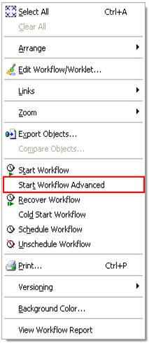
Choose the workflow instance name from the pop up window and click OK to run the selected workflow instance.
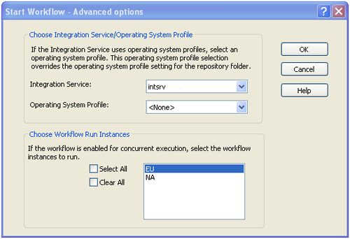
          Informatica PowerCenter Concurrent Workflow triggering
          Form the workflow monitor you can see the running instance of the workflow. As shown in below image you can see the workflow run instance, which is running concurrently.
          Informatica PowerCenter Concurrent Workflow RunningHope you enjoy this tutorial, Please let us know comments and feedback.

          Processing UNICODE Characters in Informatica PowerCenter Workflow

          $
          0
          0
          character encoding in Informatica powercenter workflow
          Couple of days back one of my friends mailed me and said, he is not able to process Arabic characters using Informatica PowerCenter workflow. You might have faced same issue in processing scripts such as Arabic, Hebrew, Chinese etc. Let discuss about how we can process such non English scripts in Informatica PowerCenter workflows.

          Before we jump into Informatica PowerCenter configuration, lets understand couple key concept behind processing different character set.

          Character Set : Is a code that pairs a set of natural language characters such as an alphabet or symbol with a set of numbers.  For example The ASCII character set, uses the numbers 0 through 127 to represent all English characters as well as special control characters. UNICODE is the widely used character set, which can represent over 110,000 characters covering 100 scripts such as Arabic and Hebrew Chinese etc..

          Character Encoding : Is an algorithm that translates a list of numbers (these number are defined in the character set) to binary so that a computer reads and displays a character in a way that humans can understand. UTF-8 is the popular encoding used for UNICODE character set.

          So from above description it is very evident that Character Set and Character Encoding are the key behind processing any foreign characters correctly. We need to have the Informatica PowerCenter Integration Service and Repository Service configured to process all the characters hat might come in your data sources.

          Integration Service Configuration

          You can choose the character set supported by the integration service during the initial configuration or you can change it later from the Administrator console.

          While Informatica PowerCenter Installation

          During  PowerCenter installation we can set the supported character set or Data movement Mode  as shown in below image. Please Check out Informatica PowerCenter Installation Guide for step by step installation instruction.
          Informatica PowerCenter Unicode Setting

          After Informatica PowerCenter Installation

          We can  change the Character Set later after PowerCenter Installation, you can do this from the Admin Console.  

          Log on to Admin Console using the admin user id and password and choose the Integration service from the Domain Navigator as shown in below image. 

          Click Edit to change the Data Movement Mode(Character Set) 
          Informatica PowerCenter Unicode Setting
          Choose 'Unicode' from the drop down list, and OK.
          Informatica PowerCenter Unicode Setting
          Read Informatica PowerCenter Installation Guide for the complete Informatica Installation Guide.

          Repository Service Configuration

          Character set of Repository Service can only be set during the service configuration. This canot be changed later. See below highlighted image and Check out the complete Informatica PowerCenter Installation Guide.
          Informatica PowerCenter Unicode Setting
          With this configuration, Informatica PowerCenter will have the capability to handle any character with in the UNICODE character set.

          Workflow Configuration

          During the configuration of each workflow, you need to choose the codepage or character encoding for  the data source and the target data. 

          You can choose codepage or character encoding from the source and target property as shown in the below image.
          Informatica PowerCenter Unicode Setting
          You can choose the code page or the character encoding of the target data as shown in below image.
          Informatica PowerCenter Unicode SettingHope you enjoyed this post and is informative. Please leave your question and comments.

          Working with Joiner Transformation and Rank Transformation

          $
          0
          0
          character encoding in Informatica  Joiner Transformation and Rank Transformation
          This tutorial shows the process of creating an Informatica PowerCenter mapping and workflow which pulls data from Flat File data sources and uses Joiner Transformation and Rank Transformation to build a consolidated sales report.

          Lets Consider the Scenario : The Sales Department wants to use data contained in flat files to build a table summarizing the revenue on each product by Product Code, Product Name, and Product Category. The weekly orders from each store are consolidated into one orders file, and the IT organization has downloaded from the Mainframe a flat file listing of each product sold by the company.

          I. Analyze the source files

          1. Launch Mapping Designer and connect to the repository.
          2. Highlight your folder and open the Source Analyzer.
          3. To import the ORDERS.TXT flat file definition into the repository, select SOURCES | IMPORT FROM FILE from the menu.
          4. Select ORDERS.TXT from the source directory.
            HINT: Be sure to set the Files of type: to All files (*.*) from the pull-down list, before clicking on OK.
          5. Set the following options in the Flat File Wizard
            1. Select the Delimited radio button.
              Informatica Analyze the source files
            2. Name the source definition ORDERS. Click on Next button.
            3. Enter the column names and specify data types and field widths as shown below.
              Informatica Analyze the source files
            4. Click on Finish.
          6. Import the PRODUCTS.TXT flat file definition into the repository and name the source definition as PRODUCTS.
          7. Verify the column names and change data types as needed to match the preceding table. The source definitions should look like the ones shown below.
            Informatica Analyze the source files

          II. Design the Target Schema

          1. Create the target table definition Tgt_ProductRevenue_x in the Target Designer and generate the SQL script for the same. Your target table definition should look like below image.
            Informatica target designer

          III. Drag Sources and Targets into the new Mapping

          1. Create a new mapping with the name M_Product_Revenue_x.
          2. Set the Mapping Designer options.
          3. Automatically create Source Qualifiers when calling source definitions into the mapping.
          4. Click OK.
          5. Drag the ORDERS and PRODUCTS source definitions from the Navigator Window into the Mapping Designer workspace. Two Source Qualifiers will be created automatically .
          6. Accept the default names.
          7. Drag the Tgt_ProductRevenue_x target definition from the Navigator Window into the workspace.

          IV. Create the Joiner Transformation

          1. Choose TRANSFORMATION | CREATE.
          2. Select the Joiner transformation from the pull down list.
          3. Name it Jnr_Orders_Products_x Make sure you are in link mode by selecting LAYOUT | LINK COLUMNS.
          4. Link the ITEM_NO, ITEM_NAME, and PRODUCT_CATEGORY ports from SQ_Products (Source Qualifier) into Jnr_Orders_Products_x (Joiner).
          5. Link the ITEM_NO, QTY, and PRICE ports: from SQ_ORDERS (Source Qualifier) into Jnr_Orders_Products_x (Joiner).
          6. Open the Joiner transformation in Edit mode.
          7. Select the Ports tab.
          8. Identify all the ports from PRODUCTS as Master ports.
            HINT: Check the M column checkbox for any one of the ports, which flow originally from the PRODUCTS source definition. 
            informatica joiner transformation
          9. Select the Condition tab.
          10. Add a new condition: ITEM_NO = ITEM_NO1.
          11. Exit the Edit Transformations dialog box by clicking the OK button.

          V. Create the Aggregator Transformation

          1. Create an aggregator transformation and name it Agg_ProductRevenue_x.
          2. Link the ITEM_NO, ITEM_NAME, PRODUCT_CA TEGORY , QTY , and PRICE from JNR_ORDERS_PRODUCTS (Joiner) into Agg_Product_Revenue_x (Aggregator).
          3. Switch to copy mode, LAYOUT | COPY COLUMNS.
          4. Copy the TOTAL_QTY and TOTAL_REVENUE ports from Tgt_ProductRevenue_x (target definition) into the Agg_ProductRevenue_x(Aggregator).
            Remainder: You are not linking these ports. Instead you are using the column names (ports) in the target table definition as a model for the names of the ports in the new Aggregator.
          5. Group by ITEM_NO, ITEM_NAME, and PRODUCT_CA TEGORY . Hint : Check the Group by columns check box under the Ports tab in the Edit Transformations box.
          6. Enter aggregate expressions for the TOTAL_QUANTITY and TOTAL_REVENUE ports and make QTY as input port: TOTAL_QUANTITY: SUM(QTY) TOTAL_REVENUE : SUM(PRICE * QTY)
          7. The final transformation should look like the one shown below.
          informatica aggregrtor transformation

          VI. Create the Rank Transformation

          1. Choose TRANSFORMA TION | CREA TE.
          2. Select Rank from the pull-down list.
          3. Name it Rnk_TopTen_x.
            Note: You can also click on the icon clip_image001[11] from the transformations toolbar to create the rank transformation.
          4. Switch to link mode LAYOUT | LINK COLUMNS.
          5. Link ITEM_NO, ITEM_NAME, PRODUCT_CATEGORY, PRICE, TOTAL_QUANTITY and TOTAL_REVENUE from Agg_ProductRevenue (Aggregator) into Rnk_TopTen (Rank).
          6. Double-click on the Rank Transformation to enter Edit mode.
          7. Select the Ports tab.
          8. Identify the TOTAL_REVENUE port as the one to rank. Hint: Check the R column. 
          9. Deselect the GroupBy options on the ITEM_NAME and PRODUCT_CATEGORY ports.
          10. Select the Properties tab.
          11. Select Top/Bottom = Top, and Number of Ranks = 10.
          12. Exit the Edit Transformations dialog box by clicking the OK button.
          13. Connect the Rank transformation to the target table. Hint: Select LAYOUT | AUTOLINK, OR Right click on the workspace and choose Autolink.
          14. Select REPOSITORY | SAVE.
          15. Given below is the final mapping.
            informatica powercenter mapping

          VII. Load the Target

          1. Create a Workflow with the name wf_ProductRevenue_x.
            1. Create a session task with the name s_ProductRevenue_x
          2. Run the Workflow.
          3. Monitor the Workflow.
          4. Verify the results for target table Tgt_ProductRevenue_x.
          Your results should look something like this

          VIII. Video Tutorial


          Hope you enjoyed this tutorial, Please let us know if you have any difficulties in trying out these exercise.

          Change Your Target XML File Name Dynamically Without Any Scripts

          $
          0
          0
          Change Your Target XML File Name Dynamically
          Just like creating flat files with dynamic file name, you might get requirements to generate XML output files with dynamic name. In this article lets see an easy method to generate XML output files with dynamically changing name.

          Lets directly jump into the mapping development.

          As the first step lets open the target XML definition in the target designer. Double click the XML definition to open it in the XML editor.

          XML Editor opens as shown in below image.
          XML Editon in Informatica PowerCenter
          Click and highlight the root node(X_cus_customerinfo) of the XML definition. Go to the menu XML Views and click on Create FileName Column as shown below. This will create an additional column in the XML target definition.
          XML Editon in Informatica PowerCenter
          Save and close the XML Editor. You will see the FileName port is created in the XML Target definition as in below image.
          XML target definition in Informatica PowerCenter
          Build your mapping with an expression transformation as shown in below image to generate the dynamic file name. Map the column from the expression transformation to FileName port in XML Target definition.

          Hint : In below mapping example, XML file name is dynamically changed based on the Customer STATE. The output file names will be like CA.XML, NY.XML, NJ.XML...
          image
          Now Create the workflow, not any special setting is required at the session or workflow level.
          Note : You can leave the Output Filename session property with the default value.

          Hope you enjoyed this tutorial and is helpful. Please leave you questions and commends, I will be more than happy to help you.

          Informatica PowerCenter Designer Features for Improved Productivity

          $
          0
          0
          Informatica PowerCenter Productivity tools
          As a Informatica PowerCenter developer, you will be spending most of your development time with Mapping Designer than any other client tool. So it is really important to understand the features of the tool to improve your development productivity. Lets discuss couple of top productivity features of PowerCenter Mapping Designer.

          1. Search Tool

          The Mapping Designer includes the Find Next and Find in Workspace tools to help find columns or ports in repository objects. Very helpful feature to locate a transformation or column in large mappings.

          Find Next : Use the Find Next tool to search for a column or port name in Transformations, Mapplets, Source definitions or Target definitions. You will see the Search tool in the tool bar like in the below image or from the manu Edit > Find Next.

          This tool can be used just like shown in below image.
          Informatica PowerCenter Search Tool
          Find in Workspace: The Find in Workspace tool searches for a column name or transformation name in all transformations in the workspace.  You will see the Search tool in the tool bar like in the below image or from the manu Edit > Edit > Find in Workspace.

          Informatica PowerCenter Search Tool
          Find in Workspace dialog box opens up as sown below. Like shown in the image, you can search for the Fiels, Table (Transformation).  It shows all the instances of the searched column.

          Informatica PowerCenter Search Tool

          2. Auto Linking Ports

          You can automatically link ports between transformations either by position or by name. You can invoke this tool from the menu Layout > Autolink or by right clicking the workspace and choosing Autolink.

          When you link by position, the Designer links the first output port to the first input port, the second output port to the second input port, and so forth.

          You can link ports by name in the Designer. The Designer adds links between input and output ports that have the same name. As shown in below image ports between SRT_GROUP_CUSTOMERS and EXP_FILE_NAME are linked automatically by name.
          Informatica PowerCenter port Link Tool
          When you link ports automatically by name, you can specify a prefix or suffix by which to link the ports. Use prefixes or suffixes to indicate where ports occur in a mapping.

          For example, a mapping includes a port in the Source Qualifier called CUST_ID and a corresponding port in a Union transformation called CUST_ID1. ‘1’ is the suffix you specify when you automatically link ports between the Source Qualifier and Union transformation.

          Like shown in below image you can setup properties in the autolink dialogbox.
          Informatica PowerCenter port Link Tool
          Ports from Source Qualifies has been mapped to the Union Transformation as shown in below image.
          Informatica PowerCenter Mapping

          3. Propagating Port Attributes

          You propagate any attributes such port name, datatype, precision, scale, and description as throughout the mapping. For example if you change the precision of a port, you will have to apply the same precision to all remaining transformations as well. In such cases you propagate post attributes.

          The Designer propagates ports, expressions, and conditions based on the following factors:
          • The direction that you propagate : You can propagate changes forward, backward, or in both directions.
          • The attributes you choose to propagate : You can propagate port name, datatype, precision, scale, and description.
          • The type of dependencies : You can propagate changes to dependencies along a link path or to implicit dependencies within a transformation.
          You can choose the properties mentioned above from the dialogbox shown below. You can invoke this dialogbox by right clicking any transformation ports of a mapping open in the workspace.
          Informatica PowerCenter Mapping propagate attribute

          You can see from below image, you can see the preview of the port propagation highlighted in green.

          4. Viewing Dependencies

          Source Column Dependencies : When editing a mapping, you can view source column dependencies for a target column. Viewing source column dependencies lets you see from which source columns a target column receives data.

          To view column dependencies, right-click a target column in a mapping and choose Show Field Dependencies.
          Informatica PowerCenter Mapping Viewing Dependencies
          Here you can see CUST_NAME is dependent on both LAST_NAME, FIRST_NAME column from the Customer source table.
          Informatica PowerCenter Mapping Viewing Dependencies
          Object Dependencies : You may need to find out the dependent objects for any chosen object. Right click on any object to invoke the Dependency dialogbox shown below.
          Informatica PowerCenter Object Dependencies

          5. Link Path

          When editing a mapping, you may want to view the forward and backward link paths to a particular port. Link paths allow you to see the flow of data from a column in a source, through ports in transformations, to a port in the target.

          To view link paths, highlight a port and right click on it. Select the Select Link Path option. You can choose to view either the forward path, backward path, or both as shown in below image.


          6. Overview Window

          An optional window to simplify viewing workbooks containing large mappings or a large number of objects. Outlines the visible area in the workspace and highlights selected objects in color. This option is really helpful when working with mapping having large number of transformations.
          Informatica PowerCenter Designer Overvoew Window
          To open the Overview window, click View > Overview Window.

          7. Iconizing Workspace Objects

          Iconizing Workspace Objects feature can be used in large mappings to see a the whole picture of the mapping and will help navigate to different transformations in the mapping easily.

          Click Layout > Arrange All Iconic to Iconic the objects.
          Informatica PowerCenter Mapping Iconizing Viewing

          8. Table Definition Options

          Table definition option can be used to specify the properties you see in each object such as transformations, source, target definition. You might need to see the Xpath property of an XML transformation or Level Property of a Normalizer transformation.

          You can change these setting using target definition options. Click Tools > Options for this option.
          Informatica PowerCenter Mapping Properties

          9. Copying Designer Objects

          You can copy and paste objects in Informatica PowerCenter Designer tool. These operations can be done across folders as long as both the folders are open. You can use Ctrl + C and Ctrl + V to do these operations or use the Edit Menu.

          10. Comparing Objects

          You can compare two repository objects of the same type to identify differences between the objects through the Designer. For example, you may want to use a target definition in a mapping, but you have two target definitions that are similar. You can compare the target definitions to see which one contains the columns you need. When you compare two objects, the Designer displays their attributes side-by-side.

          Hope you enjoyed this tutorial, Please let us know if you have any questions and let us know if you are using any other productivity tips.

          Data Cleansing and Standardization Using Regular Expression

          $
          0
          0
          Informatica PowerCenter Productivity tools
          Data Quality is one of the major priorities of any data warehouse or any data integration project. We use different tools for data quality and data standardization implementation. But tools may not be the right solution for small projects which involve couple of data feeds. Regular Expression is an alternative approach for such small projects. In this article lets discuss about data quality implementation using Regular Expression or RegEx in Informatica PowerCenter.

          What is Regular Expression or RegEx

          A regular expression provides a concise and flexible means to recognize strings of text, such as particular characters, words, or patterns of characters. Regular expressions are used when you want to search for specify lines of text containing a particular pattern.

          Just like simple string search operators (%, _ ) used in SQL, Regular Expressions have a full set of matching operators. The following table provides regular expression syntax guidelines.

          Syntax
          Description
          .
          A period matches any one character.
          [a-z]
          Matches one instance of a character in lower case. For example, [a-z] matches ab. Use [A-Z] to match characters in upper case.
          \d
          Matches one instance of any digit from 0-9.
          \s
          Matches a whitespace character.
          \w
          Matches one alphanumeric character, including underscore (_)
          ()
          Groups an expression. For example, the parentheses in (\d-\d-\d\d) groups the expression \d\d-\d\d, which finds any two numbers followed by a hyphen and any two numbers, as in 12-34.
          {}
          Matches the number of characters. For example, \d{3} matches any three numbers, such as 650 or 510. Or, [a-z]{2} matches any two letters, such as CA or NY.
          ?
          Matches the preceding character or group of characters zero or one time. For example, \d{3}(-{d{4})? matches any three numbers, which can be followed by a hyphen and any four numbers.
          *
          Matches zero or more instances of the values that follow the asterisk. For example, *0 is any value that precedes a 0.
          +
          Matches one or more instances of the values that follow the plus sign. For example, \w+ is any value that follows an alphanumeric character.

          Regular Expression Example

          Following regular expression finds 5-digit U.S.A. zip codes, such as 93930, and 9-digit zip codes, such as 93930-5407

                             \d{5}(-\d{4})? 

          \d{5} refers to any five numbers, such as 93930. The parentheses surrounding -\d{4} group this segment of the expression. The hyphen represents the hyphen of a 9-digit zip code, as in 93930-5407. \d{4} refers to any four numbers, such as 5407. The question mark states that the hyphen and last four digits are optional or can appear one time.

          Regular Expression Implementation in Informatica PowerCenter

          Informatica PowerCenter provides couple of functions to implement regular expression. These function can be used just like any other function in an expression. Lets see the functions in detail.

          REG_EXTRACT: Extracts sub patterns of a regular expression within an input value. For example, from a regular expression pattern for a full name, you can extract the first name or last name.

          Syntax : REG_EXTRACT ( subject, pattern, subPatternNum )
          ExampleREG_EXTRACT( Employee_Name, '(\w+)\s+(\w+)', 2 ), Extracts the last name from the Employee Name Column.

          REG_MATCH : Returns whether a value matches a regular expression pattern. This lets you validate data patterns, such as IDs, telephone numbers, postal codes, and state names. 

          Syntax : REG_MATCH ( subject, pattern )
          Example : REG_MATCH (Phone_Number, '(\d\d\d-\d\d\d-\d\d\d\d)' ),  This expression to validate the 10 digit telephone numbers

          REG_REPLACE: Replaces characters in a string with a another character pattern. By default, REG_REPLACE searches the input string for the character pattern you specify and replaces all occurrences with the replacement pattern. You can also indicate the number of occurrences of the pattern you want to replace in the string.

          Syntax : REG_REPLACE ( subject, pattern, replace, numReplacements )
          Example : REG_REPLACE( Employee_Name, ‘\s+’, ‘ ’),  Removes additional spaces from the Employee name

          Real Time Scenario

          Consider a scenario where you get a flat file with a date column, which comes in three different formats  MM-DD-YYYY, YYYY-MM-DD and DD/MM/YYYY.  We need to load this date column to the target in DD/MM/YYYY format.

          Expression given below will check for the date format from the DATE column and convert it to DD/MM/YYYY format.

                            IIF(REG_MATCH(DATE,'(\d\d\/\d\d/\d\d\d\d)'),TO_DATE(DATE,'dd/mm/yyyy'),
                                  IIF(REG_MATCH(DATE,'(\d\d-\d\d-\d\d\d\d)'),TO_DATE(DATE,'mm-dd-yyyy'),
                                        IIF(REG_MATCH(DATE,'(\d\d\d\d-\d\d-\d\d)'),TO_DATE(DATE,'yyyy-mm-dd'))))


          Apart from the small given above, there is a lot of standard RegEx available for validations such as email, Phone Number, Zip Code etc.

          eMail :- ^[a-z0-9_\+-]+(\.[a-z0-9_\+-]+)*@[a-z0-9-]+(\.[a-z0-9-]+)*\.([a-z]{2,4})$
          Phone Number :- ^[2-9][0-9]{2}-[0-9]{3}-[0-9]{4}$
          Zip Code :-  ^\d{5}(-\d{4})?$

          Like you see in the table above, RegEx has a rich list of operators, which helps create any complex data validation rules. 

          We can make these validations as a reusable expression and can be used as the data validation standard across different projects.

          Hope you enjoyed this tutorial, Please let us know if you have any questions.

          Change Data Capture (CDC) Implementation Using CHECKSUM Number

          $
          0
          0
          Change Data Capture Implementation Using CHECKSUM Number
          Typically we use a date column or a flag column to identify the change record for change data capture implementation. But there can be scenarios where you source do not have any columns to identify the changed records especially when working with legacy systems. Today in this article lets see how to implement Change Data Capture or CDC for such scenarios using checksum number.

          What is Checksum

          A checksum is a value used to verify the integrity of a file or a data. Checksums are typically used to compare two sets of data to make sure they are the same. If the checksums don't match those of the original file or data, the data may have been altered.

          How to find Checksum

          Informatica provides the function MD5() for Checksum generation. This function returns a unique 32-character string of hexadecimal digits 0-9 and a-f.

          Syntax : MD5( value )
          Return : Unique 32-character string of hexadecimal digits 0-9 and a-f.

          Informatica Implementation

          Design Scenario

          Lets consider a workflow to load CUSTOMER table from a  flat file, which is generated from legacy mainframe system. Any new customer information will be inserted and any changed customer information will be updated else rejected to bad file. Note that the source file do not have any indicator to identify the changed record.

          Datamodel Needs

          Apart from the customer attributes columns, we need to create an additional database table column to store the CHECKSUM number. It is 32 character hexadecimal value. So add the column to the CUSTOMER table and below is the target table definition.
          Informatica PowerCenter Target Definition

          Informatica Mapping

          Lets start with the mapping. Create CHECKSUM using MD5() function in the expression as sown in below image.
            • MD5(CUST_NAME || ADDRESS1 || ADDRESS2 || CITY || STATE || TO_CHAR(ZIP))
          Informatica PowerCenter CheckSum MD5
          Now create a LookUp transformation to get CUST_ID and CHK_SUM_NB from the target table. Use the LookUp Condition IN_CUST_ID = CUST_ID
          Informatica PowerCenter LookUpTransformation
          Now find out the records for INSERT, UPDATE using the columns from the lookUp Transformation with the expressions below.

          INSERT : ISNULL(LKP_CUST_ID)
          If the Customer is not existing in the target table, set the record for INSERT.

          UPDATE : NOT ISNULL(LKP_CUST_ID) AND CHK_SUM_NB <> LKP_CHK_SUM_NB
          If the Customer is existing in the target table and the Checksum of the source record is different from the lookup, set the record for UPDATE.

          REJECT : Any other records not satisfying the above conditions will be passed on to the DEFAULT group and ignored.

          Now add the Router Transformation with two groups with the expressions explained above.
          Informatica PowerCenter Router Transformation
          After the Router Transformation is added the mapping looks like in below image.
          Informatica PowerCenter Router Transformation
          Map the columns from INSERT and UPDATE group to both target instances, including CHK_SUM_NB to the target table.
          Change Data Capture (CDC) Implementation Using CHECKSUM Number
          Note : CHK_SUM_NB is Inserted and Updated into the target table, this value is used by the lookup to determine the insert and update.

          All you left now is to create and run the workflow. Hope you enjoyed this tutorial. Please let me know if you have any questions or comments.

          Informatica PowerCenter Installation Known Issues and Solution

          $
          0
          0
          Change Data Capture Implementation Using CHECKSUM Number
          Since we published the article on informatica installation and configuration, we have been getting questions on different installation issues.  So here we thought of writing an article with a consolidated list of issues faced during the installation.  This will be a live article and will be updated as and when we get new issues from the readers.

          Database driver event...Error occurred loading library [pmora8.dll]

          Cause

          This error occurs when the Oracle client installed in the Windows machine is 32-bit and PowerCenter is 64-bit.

          Solution

          To resolve this issue re-install the Oracle client 64 bit on the machine where PowerCenter 64-bit server is running.

          To check which version you use, run TNSPING.

          For Oracle 10g, you should have: 32 bits Oracle
          C:\oracle\product\10.2.0\client_1\BIN>tnsping
          TNS Ping Utility for 32-bit Windows: Version 10.2.0.3.0 - Production on 04-J┌N-2
          008 08:52:08

          PowerCenter Informatica Services does not start on Windows

          Cause

          This issue is caused because the User specified during the installation is not Part of Operating System and Log on as a Service privilege and the user is not part of the Administrator Group.

          Solution

          Confirm that the Windows user specified in This Account has the following privileges:
          • Act as Part of the Operating System 
          • Log on as a Service 
          by doing the following:
          1. Go to Start > Settings > Control Panel > Administrative Tools > Local Security Policy . 
          2. Select Local Policies > User Rights Assignment . 
          3. Add the user to Act as Part of the Operating System and Log on as a Service.

          ERROR: "This installation package can not be opened.." when installing PowerCenter 9.x

          Cause

          This issue occurs because of the native zip extraction package on Windows, which results in an incomplete extraction with large files or big file names.

          Solution

          To resolve this issue, use another zip utility such as WinZip, Peazip, or WinRar to unzip the installation package.

          ERROR: "Unable to handle request because repository content do not exist" when starting the Integration service

          Cause

          This error occurs when the PowerCenter Repository Service is running on Exclusive Mode

          Solution

          To resolve this issue, change the Repository to run on the Normal Mode and restart both the Repository and Integration Services.

          Please let us know about any new issues you come across during the Informatica PowerCenter Installation. We wil be more than happy to help you.

          SCD Type 3 Implementation using Informatica PowerCenter

          $
          0
          0
          Change Data Capture Implementation Using CHECKSUM Number
          Unlike SCD Type 2, Slowly Changing Dimension Type 3 preserves only few history versions of data, most of the time 'Current' and Previous' versions. The 'Previous' version value will be stored into the  additional columns with in the same dimension record.  In this article lets discuss the step by step implementation of SCD Type 3 using Informatica PowerCenter.

          The number of records we store in SCD Type 3 do not increase exponentially as we do not insert a record for each and every historical record. Hence we may not need the performance improvement techniques used in the SCD Type 2 Tutorial.

          Understand the Staging and Dimension Table.

          For our demonstration purpose, lets consider the CUSTOMER Dimension. Here we will keep previous version of CITY, STATE, ZIP into its corresponding PREV columns. Below are the detailed structure of both staging and dimension table.

          Staging Table

          In our staging table, we have all the columns required for the dimension table attributes. So no other tables other than Dimension table will be involved in the mapping. Below is the structure of our staging table.
          Informatica Source Definition

          Key Points 

            1. Staging table will have only one days data.
            2. Data is uniquely identified using CUST_ID.
            3. All attribute required by Dimension Table is available in the staging table

            Dimension Table

            Here is the structure of our Dimension table.
            Informatica Target Definition

            Key Points

              1. CUST_KEY is the surrogate key.
              2. CUST_ID is the Natural key, hence the unique record identifier.
              3. Previous versions are kept in PREV_CITY, PREV_STATE, PREV_ZIP columns.

            Mapping Building and Configuration

            Lets start the mapping building process. For that pull the CUST_STAGE source definition into the mapping designer.
            Slowly Changing Dymention Type 3
            Now using a LookUp Transformation fetch the existing Customer columns from the dimension table T_DIM_CUST. This lookup will give NULL values if the customer is not already existing in the Dimension tables. 

            • LookUp Condition : IN_CUST_ID = CUST_ID
            • Return Columns : CUST_KEY, CITY, STATE, ZIP
            Slowly Changing Dymention Type 3
            Using an Expression Transformation identify the records for Insert and Update using below expression. Additionally, map the columns from the LookUp Transformation to the Expression as shown below.  With this we get both  the previous and current values of the CUST_ID.
              • CREATE_DT :- SYSDATE
              • UPDATE_DT :- SYSDATE
              • INS_UPD :- IIF(ISNULL(CUST_KEY),'INS', IIF(CITY <> PREV_CITY OR STATE <> PREV_STATE OR ZIP <> PREV_ZIP, 'UPD'))   
            Note : If in case there are too many columns to be compared  to build the INS_UPD logic, make use of CheckSum Number (MD5() Function) to make it simple.       
              Slowly Changing Dymention Type 3
              Map the columns from the Expression Transformation to a Router Transformation and create two groups (INSERT, UPDATE) in Router Transformation using the below expression. The mapping will look like shown in the image.
                • INSERT :- IIF(INS_UPD='INS',TRUE,FALSE)
                • UPDATE :- IIF(INS_UPD='UPD',TRUE,FALSE)
              Slowly Changing Dymention Type 3

              INSERT Group

              Every records coming through the 'INSERT Group' will be inserted into the Dimension table T_DIM_CUST.

              Use a Sequence generator transformation to generate surrogate key CUST_KEY as shown in below image. And map the columns from the Router Transformation to the target. Leave all 'PREV' columns unmapped as shown below image.
              Slowly Changing Dymention Type 3
              Note : Update Strategy is not required, if the records are set for Insert.

              UPDATE Group

              Records coming from the 'UPDATE Group' will update the customer Dimension with Current customer attributes and the 'PREV' attributes. Add an Update Strategy Transformation before the target instance and set it as DD_UPDATE. Below is the structure of the mapping.

              Slowly Changing Dymention Type 3
              We are done with the mapping building and below is the structure of the completed mapping.
              Slowly Changing Dymention Type 3

              Workflow and Session Creation

              There is not any specific properties required to be given during the session configuration. 
              informatica worklet
              Below is a sample data set taken from the Dimension table T_DIM_CUST. See the highlighted values.
              Slowly Changing Dymention Type 3
              Hope you guys enjoyed this. Please leave us a comment in case you have any questions of difficulties implementing this.

              Informatica PowerCenter Repository BackUp and Restore

              $
              0
              0
              Change Data Capture Implementation Using CHECKSUM Number
              Informatica PowerCenter administrators regularly backup the repository contents to prevent any data loose due to hardware or software problems. When the repository contents is backed up, it saves all the contents as a binary file which includes all the repository objects such as mapping, sessions, workflows etc. These binary files can be used to restore the contents if in case of any failure. In this article lets discuss the step by step process to backup and restore a PowerCenter Repository.

                    • BackUp the Repository
                    • View the BackUps
                    • Restore the Backup

              BackUp the Repository

              Step : 1

              Logon to Administrator Consol using your Admin User ID and Password as shown in below image.
              Informatica PowerCenter Repository BackUp and Restore

              Step : 2

              Choose the repository, which you need to backup.  Click on 'Actions' at the right top, Then Actions -> Repository Contents -> Back Up

              Informatica PowerCenter Repository BackUp and Restore

              Step : 3

              Provide the User Name, Password and other details as given in the below image. Provide the optional information highlighted, if required.

              Informatica PowerCenter Repository BackUp and Restore

              View the BackUps

              You can view the already backed up repository files versions. 

              Step : 1

              After you log on to Administrator Console, Go to Actions -> Repository Contents -> View Backup Files as shown in below image.


              Informatica PowerCenter Repository BackUp and Restore

              Step : 2

              A popup window appears with the list of previously backed up files.

              Informatica PowerCenter Repository BackUp and Restore

              Restore the Backup

              To restore the repository contents from a backup, there should not be any content in the repository. If you choose a repository with existing content, 'Restore' Option will not be available.

              Step : 1

              After you log on to Administrator Console, Choose the repository to which the content needs to restore. Then Go to Actions -> Repository Contents -> Restore as shown in below image.
              Informatica PowerCenter Repository BackUp and Restore

              Step : 3

              A popup window appears with the list of previously backed up files. Choose the appropriate backup file from the drop down list. Choose the optional Options as required, which is shown in below image. 

              Informatica PowerCenter Repository BackUp and Restore

              Step : 3

              Restore takes couple of minutes depending on the size of the repository contents.

              Informatica PowerCenter Repository BackUp and Restore
              Thats all for the backup restoration.
              Please let us know if you have any issues of concerns, we are more than happy to help you.
              Viewing all 98 articles
              Browse latest View live